SUMMARY
The closing operation is key to the metalworking and packaging industry. Here we develop the necessary requirements to obtain a good seal, with interchangeable components, analyzing what these are and how they should be conditioned.
INTRODUCTION AND REQUIREMENTS
INTRODUCTION:
There is a common task for the metalworking industry and the packers. It is the realization of the closure or union of the body of the container with its corresponding lid and bottom. To ensure that this work is carried out under appropriate conditions, and maintains uniform and safe levels of quality, a series of recommendations and standards are increasingly being applied, initially at the national level in each country, but which have gradually been internationalised through regulatory bodies. In this article we summarize the main conclusions of these recommendations.
This work contains the recommended specifications to be applied in the purchase of packaging and funds intended for processed products and foodstuffs. The data shown here are accepted by the main metallographic industries worldwide.
The application of these specifications makes it possible to define an interchangeability agreement, in all matters relating to the double sealing of the containers supplied by the manufacturers. Although the dimensions and tolerances detailed here are quite realistic, the indiscriminate use of them does not ensure identical results, applying a common adjustment. There are certain measures in which it is difficult to reach a unanimity of criteria, such as the radius of the bottom tray, or the minimum diameter of the inside of the curl of the same, where different values can be presented, which give rise to specific adjustments.
REQUIREMENTS:
Containers and bottoms should be manufactured, packed and transported in the most suitable way for filling, packaging and distribution of the food product for which they are intended.
Containers, loose bottoms and closure tooling for seaming machines should be sized to ensure interchangeability of components from each manufacturer, along the filling, closing, conveyor and packaging equipment, subject to the following limitations:
1- For a given model of seamer, not all container diameters and bottoms of any type can be closed using common seaming mandrels and rollers.
2- Due to variations in the dimensions of both components and machine adjustments, even within the recommended standards, it is not possible to guarantee that it will not be necessary to make adjustments between different supplies, even from the same supplier. However, it is considered that adhering to these standards would ensure that the need for adjustments is minimized.
3- The supplier of the seaming machine will provide the recommended adjustments of the machine and its set-up, for any combination of containers and bottoms. It is advised that later, when problems arise, the set-up procedure should be used as a basis for ensuring that the machine setting is correct.
DIMENSIONAL TARGETS AND TOLERANCES
At the time, the following agreements were adopted by the manufacturers for the standards listed in this paper:
– 1: “Targets” with their plus or minus tolerance. The “target” dimension to be achieved is the value that is considered ideal for each parameter. This “target” value is defined by the nominal data. 99.7% of the containers or bottoms in any lot (see note), must be within the tolerances indicated. The mean of all measures in this category should be at or near the stated “target” value. In the case of empty container height, where the defined tolerance is plus or minus 0.50 mm, the average for all measurements is expected to be within plus or minus 0.13 mm of the target measurement.
– 2: Field set (not “target”). 99.7% of containers or bottoms in any batch (see note), must be within the established field. This field is delimited by the tolerances.
– 3: Minimum value. 99.7% of the product in any batch (see note), must be at or above the minimum value established.
– 4: Pass/fail field. 99.7% of the product in any batch (see note), must be within the stated “pass/fail” dimensions.
– Dimensions shown without tolerances are tooling dimensions for reference only.
Note: A lot is defined as a supply or consignment comprising not less than 50,000 packages or 200,000 bags.
MANDRELS FOR CAN SEAMING MACHINES FOR CANS OR METAL CONTAINERS
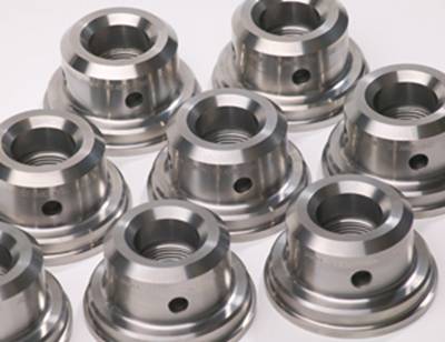
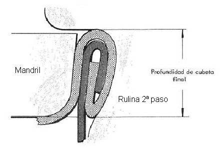
The basic part of the seaming machines is the mandrel chuck, together with the seaming rollers. This disc is adjusted to the inside of the bottom tray in a very precise way, and acts as a support, on which the material is closed by winding – or seaming – under the action of the rollers.
The dimensions of the mandrel are closely linked to those of the bottoms. Therefore, in order to ensure that the same mandrel can be used for successive supplies of the same, even if they are from different suppliers, interchangeability between them must be guaranteed, as we have already pointed out.
The mandrel has two different parts, the upper part where it is fixed to the seaming machine, whose dimensioning is defined by the manufacturer of the equipment, and the lower or active part linked to the measurements of the bottoms to be used in the seaming operation. Figure 1 shows the profile of the lower area or lip of the mandrel, depending on the containers to be closed.
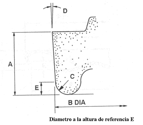
Figure No. 1: Profile of the mandrel lip
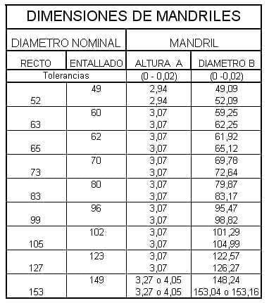
The appropriate measures of this profile, depending on the funds to be used, are shown in the attached table. In fact, a series of dimensions have been unified, whatever the diameter of the bottom to be closed. The angle of inclination of the lip “D”, the radius of the lip “C” and the reference point “E” on which the diameter measurement is to be taken are common. Therefore, the only two variable dimensions are: The height of the lip “A” and its diameter “B” at the reference point.
Common dimensions for all mandrel diameters:
Height of the reference point E = 1.05 mm
Mandrel radius C = 1 mm +0.00 / -0.05
Lip angle D = 4º +/- 10`.
In this table, the nominal diameters of the most common straight containers are differentiated in separate columns from those of the reduced – or notched – ends, since at present straight containers and those with a notched end coexist in the market.
The height “A” of the mandrel lip remains constant for many diameters, with the exception of the small and larger ones. In the latter case – diameter 153 – there are still two different heights on the market, which results in two different values of “B” diameter.
DIMENSIONS OF THE FUNDS
As we have already said, in order to allow a unification of the closing tooling for the same format, and to obtain a quality closure, whoever the container supplier is, it is necessary to maintain the same measurements in all the dimensions that affect the making of the closure. For this purpose, work has been carried out for many years between manufacturers, trade associations, organisations, etc. and today a good degree of standardisation has been achieved.
In the drawing nº 2, the measures for round bottoms of canning containers, of the conventional type, are delimited, not including the easy-open ring-pull lids. Respecting these measures, it is possible to use the above mandrels with good results.
Figure no. 2: Basic measures of a fund related to closure
It should be clarified that the closures are classified into seven different types, depending on the dimensions of their different components (body and bottom hooks, closure height, overlapping,…). The smallest of these is the OIII and the largest is the IV . The first one (OIII) would be a mini closure for very small containers with little responsibility and the last one (IV) for big size brasses. The most commonly used types are OI, I and II, which cover normal container sizes. It happens that the same format can be found on the market with one or another type of closure. For example diameter 73 in types OI and I.
Keep in mind that when you change the type of closure, the dimensions of the backgrounds linked to it and also the body tab are modified. Therefore, each user must be very clear about which type of closure he wants to use and link the container supplies to it.
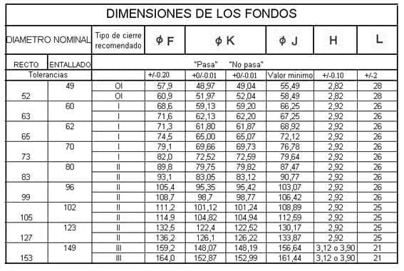
The following table shows the measurements of the conventional bottoms, related to their closure, standardized to achieve interchangeability of components. In order not to make the table too complex, only the measurements for the most usual type of fastener in each case have been shown, which is indicated in the column “Recommended type of fastener”.
As with the mandrels, we have differentiated between straight container diameters and values for notched ends. Therefore, the “notched” column does not reflect the dimensions of containers but of reduced ends.
The diameter “F”, which is the outside diameter, defines the amount of material available to make the bottom hook in the seamer, and influences the sizing of many parts of the seamer (bottom feeder, starwheels, etc.). It is a basic measurement of the lid. There are a series of formulas that link the different dimensions of the closure elements, i.e. the dimensions of the mandrel with those of the cap or flange. For example, the diameter “F” is related to the diameter of the mandrel “B” through the following expressions:
For closure type OI: F = B + 8.76
For closure type I: F = B + 9.36
For closure type II: F = B + 9.88
For closure type III: F = B + 10.92
In the case of the “K” diameter, which is the mandrel adjustment diameter, and therefore the fundamental one for the seal, the maximum and minimum values have been expressed, which correspond to the “pass”, “fail” of the quality control gauges of this measurement. The tolerances shown in the “pass” and “fail” columns are the construction tolerances of the corresponding gauges. The formula linking this measurement to the diameter of the mandrel at the reference point is as follows:
Bottom diameter up to 99: “Pass” K = B – 0.12/ “Fail” K = B – 0.05
Diameter of bottoms greater than 99: “Pass” K = B – 0.17 / “Fail” K = B – 0.05
The “J” dimension , the diameter of the inside of the curl, is of relative importance, and its purpose is to prevent interference with the body flange. That is why only its minimum value is reflected. The formula to determine the value of “J” as a function of the diameter “B” of the mandrel varies according to the type of seal selected, and is as follows:
For closure type OI: J = B + 6.40
For closure type I: J = B + 7.00
For closure type II: J = B + 7.60
For closure type III: J = B + 8.40
This is because as the type of closure increases, so does the flange and therefore more space must be left for its location inside the flange of the lid.
The cell height or depth “H” should be measured at three points equidistant from the bottom and the average of the three readings should be found. This average is also a basic dimension and is linked to the height of the mandrel in the following terms:
Bottom diameters 49 and 52: A = H + 0.12
Remaining diameters: A = H + 0.15
The “L” dimension , pile height, is not given in millimeters, but in the number of bottoms that fit in 2″ (50.8 mm) and is measured with a gauge. In another article, complementary to this one, we will detail the design, sizing and use of the gauges necessary to control these dimensions, as well as others that we will comment below, although already in the work:
– Dimensional control of funds can be seen to a good extent this matter
In the bottoms there are also two measures that remain constant in all diameters, these are:
Height of reference point “E” = 1.05 mm
Trough inner radius “G” = 0.95 mm + 0.05 / – 0.00
The position or height of the reference point “E” is the same on the bottom as on your chuck.
The inner radius of the trough “G” is equal to the center of the die punch, and its value is 0.05 mm smaller than that of the locking mandrel “C”, but with the tolerance changed.
CONTAINER DIMENSIONS
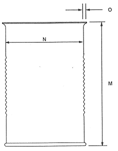
Few of the package measures are related to the closure, in fact only three:
Height: It must be uniform throughout the batch, in order to obtain an analogous compressive stress in all the containers during the sealing process.
– Tab: Its dimension defines the measures of the hook of the body, therefore it is a very important value to control.
– Inner diameter: In its extreme zone, the one corresponding to the flange, it specifies the adjustment between the bottom to be closed and the container.
It is therefore necessary to standardize their values in order to obtain an interchangeability of components. Drawing No. 3 shows the three dimensions mentioned above for a three-piece container.
Figure no. 3: Dimensions of a container with impact on the closure
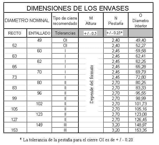
In the following table we indicate the values of these measures, but first we should make the following comments:
1º.- There is so much diversity of container heights in the market that it is not possible to list them, we only indicate the tolerance applicable to them. The height must be measured with suitable equipment – see control gauges – and in an area away from the side seam.
2º.- The width of the flange varies with the type of fastener, therefore its value is linked to it. It must be measured from the reference point, located 2.5 mm from the edge. It will be taken as a value the average of two measurements at 180º, at least 10 mm away from the side seam.
3º.- The inner diameter of the container is not a critical measure in relation to the closure, although it is in relation to the capacity of the container. Therefore in this work, focused on the first factor, we will indicate the value of the diameter as a reference, but without reflecting tolerances. As a general criterion, the bottom should fit slightly under pressure on the body. An easy test is that once the bottom has been placed on the body and lightly pressed, if the assembly is turned upside down, the bottom should not fall out.
In the case of sausage packaging, the criteria to be followed are the same as for three-piece cans.
CLOSING
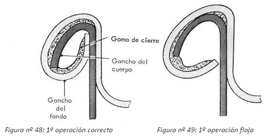
A “closure” or “double closure” is defined as the joint resulting from interlocking the end of the body of a container with its bottom or lid. This connection is made by a crimping or double crimping process, i.e. with a double safety wall. It must be perfectly airtight.
This section recommends the operating standards for double seals, for different container diameters and bottoms, as well as details of the parameters and the points at which they should be measured.
These parameters are divided into two categories:
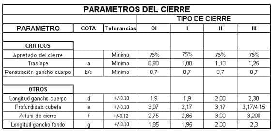
Critical: These are certain measures of the double seal whose values must be met to ensure the adequacy of the double seal.
Others: These are the parameters that serve as a means to reach the critical ones, but allow a certain flexibility in their measurement without detriment to the quality of the closure.
When purchasing a new seaming machine, the purchaser must determine from the supplier the seaming standard he wants to implement in the new equipment.
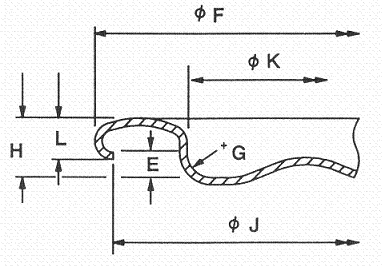
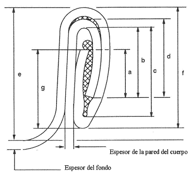
There may be some differences of opinion in defining which are the important measures or values to control in a double lock, including “critical” and “other”. We prefer the ones shown in the form of dimensions in the drawing nº 4.
Figure no. 4: Measurements of a fastener
The values of the seal parameters shall be obtained, in the case of three-piece type packs, as the average of two measurements at the 2 o’clock and 10 o’clock positions, taking 12 o’clock as the side seam position. For stuffed containers, both measurements should be taken at 180º.
In addition to the bounded measures, there are two values to be determined by calculation, both considered critical, which are:
A.-Lock Thickness Ratio: Also referred to as “Lock Tightness”. It measures the compactness of the seal, comparing the theoretical thickness with the real thickness, taking into account the contribution of the composite thickness. For this purpose, the thickness of the seal was measured at the most unfavourable point of its perimeter. Three complementary criteria can be used to calculate the ratio:
a.- Applying the following formula:
(3ef + 2ec) / actual thickness > 0.8
Where “ef” is the thickness of the bottom, and “ec” is the thickness of the body wall.
This formula can be stated: “The thickness of the five walls of the closure, divided by the actual thickness must be greater than the quotient 0.7”.
b.- Applying this other formula:
Actual Thickness = ( 3 ef + 2ec + 0.15 ) +/- 0.05
0.15 millimetres is the value of the “free space”, which must be filled by the rubber gasket.
c.- Evaluation of wrinkles of the bottom hook.
In the generation of the closure there are always wrinkles in the hooks, especially in the bottom hook, which is the one that tucks the most material inwards. The height – also called length – of the bottom hook that is free of wrinkles is an indicator of the tightness of the seal. This degree of tightness is indicated as the length of the wrinkle-free bottom hook, expressed as a percentage of the total length of the bottom hook. This indicator cannot be measured, it must be estimated visually, and as it is a subjective assessment, a certain amount of experience is required to evaluate it correctly. When there are no wrinkles on the hook, the tightness is 100% and when the wrinkle occupies the entire height of the hook it is 0%. Its minimum value must be 75%, always referred to the worst point on the bottom hook, paying special attention to both sides of the side weld joint area.
Any of the three procedures is valid, although the most traditional and widely used is the evaluation by the wrinkles on the inside of the bottom hook. In the first two cases the measurements will be made in millimetres.
B.-Body hook penetration. Determine the ratio between the length of the hook of the body “b” and the length of the inside of the fastener “c”, according to the expression
Penetration = b / c > 0.7
The following table summarizes the recommended values of these parameters, divided into “critical” and “other”, for the types of closure mentioned in this work
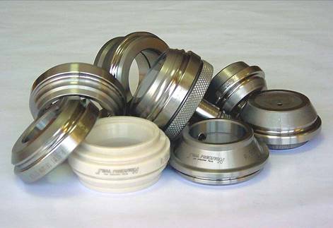
For the control of these measurements it is necessary to use a series of specific gauges, which will be the subject of another article complementary to this one.
The following material has been taken into account for the realization of this work:
– SEFEL” Standards (European Secretariat of Lightweight Metal Packaging Manufacturers)
– Recommended Industry Specifications for Open Top Processed Food Cans” developed by the MPMA (Metal Packaging Manufacturers Association).







0 Comments