

– By clicking here you can access the 1st part of this work.
– By clicking here you can access the 2nd part of this work.
3rd delivery CLOSING THEORY
6º.- ACCEPTABILITY OF THE CLOSING (Critical parameters)
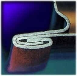
The integrity of the double seam is of crucial importance, and the minimum levels of acceptability are essentially the same for both irregular and cylindrical cans.
Incidentally, there are two aspects of the construction of the closure, which produce a hermetic seal. The primary sealing area is the one originated by the edge of the body hook embedded inside the compound, housed inside the bottom hook. The secondary seal is the area of metal overlap between the body and bottom hooks on the inside of the joining seam.
The critical parameters of acceptability of the closure are:
1º.-Tightening of the seal (2nd operation pressure):
The effect that the 2nd operation pressure has on the seal is also referred to as seal tightening. The seal must be so tight as to ensure that the rubber, initially contained in the bottom flange, and which during the seal fills the empty spaces in the seal, is compressed between the hooks, the body hook being embedded in it.
Due to the nature of the closing operation, the formation of wrinkles on the inside of the bottom hook is inevitable during the first operation, but they disappear almost completely during the second operation. The remaining ones can be seen with the naked eye and give an indication of the degree of tightness of the fastener. The presence of pronounced wrinkles can cause slight leaks, although if they are slight they do not practically affect the tightness of the seal. Therefore, a rough judgement of the tightness of the seal can be made by observing the residual wrinkles that result or may result in the second operation. See figure nº 42.

Figure no. 42: Evaluation of wrinkles as % of bottom hook height
The length of the bottom hook that is free of wrinkles is an indicator of the tightness of the seal. This degree of tightness is indicated as the length of the wrinkle-free bottom hook, expressed as a percentage of the total length of the bottom hook. This indicator cannot be measured, it must be estimated visually, and as it is a subjective assessment, a certain amount of experience is required to evaluate it correctly.
When there are no wrinkles on the hook, the tightness is 100% and when the wrinkle occupies the entire height of the hook it is 0%. This degree of tightness is a critical parameter of the quality of the closure. Its minimum value must be 75%, always referring to the worst point on the bottom hook, paying special attention to both sides of the area of the side seal joint. For non-round containers, a minimum value of 60% of the degree of tightness is acceptable. Wrinkles should be smooth in the form of undulations.
The proportion of wrinkles will be smaller the larger the diameter of the container. This is palpably evident in rectangular containers, where there are no wrinkles on the straight sides, but their presence is very accentuated in the curves of the corners, which are of small radius. Within the same format, the greater or lesser intensity of wrinkles depends on the pressure of the second operation roller. Small wrinkles are filled by the rubber gasket, which is one of its main applications.
There is a clear tendency to decrease the thickness of the bottom for unavoidable cost reduction imperatives, the ability to achieve the absence of wrinkles becomes much more difficult, and therefore complicates the task of correctly determining the evaluation of the tightness of the closure. We will return to this aspect later.
There are other types of undulations or deformations on the bottom hook, which should not be confused with those related to the degree of compactness. Some of them are shown in figures 43 and 44.
Thus in drawing no. 43, letters A, B, C and D show the typical corrugations of the seal to an acceptable degree. The bulge E is caused by an excessive accumulation of rubber at that point, which is not desirable. Point F has a small ridge on the cutting edge of the bottom hook, caused by excessive pressure from the second operation, which can lead to a lamination of the seal, a dangerous defect.

Figure no. 43: Different types of wrinkles on the bottom hook
In addition to these, there are other types of wrinkles that are undesirable and should be avoided, as they are a symptom of an anomaly, such as those shown in drawing No. 44.

Figure nº 44: Undesirable folds and wrinkles
Large isolated wrinkle: Shows that the material has not been picked up evenly.
V” wrinkle: It presents a wave inversion. The normal wrinkles are slightly concave, while the inverted “V” wrinkles are convex and therefore in relief on the surface of the bottom hook.
Crease: This is a step in the face of the bottom hook, with a risk of micro-leakage.
Free space:
In addition to checking the tightness of the fastener by evaluating the ripples or wrinkles of the bottom hook, there is another way to do this, which is to measure the thickness of the fastener, and compare it to the sum of the five thicknesses of metal that the fastener encompasses. It will give us an idea of the free space, which should be filled with rubber in normal conditions, but may be empty if it is very large.
Free space = E – ( 2 Gc + 3 Gf)
Where E is the actual thickness of the seal, Gf is the thickness of the bottom metal and Gc is the thickness of the body metal.
The “compactness” is an index, which is also used to express the degree of contact of the layers of tinplate forming the closure. It is therefore closely related to the free space. It is expressed by:
Compacity = C = ( 2 Gc + 3 Gf) x 100
Another way to express the free space would be:
Free space = (100 – C) x E
A tight seal will have low clearance and high compactness. Accordingly, the closure can be classified as follows:
– Very good………………………. C > 85% C 85% C 85% C 85% C 85% C 85
– Well ……………………………. 75% < C < 85%
– Dangerous…………………………. C < 75%.
This measure of compactness is valid only for round containers, and not the type used in carbonated beverages or beer, where the internal pressure is high and requires higher compactness values. In the case of rectangular and oval-shaped containers, which have a somewhat higher composite weight, a minimum compactness value of 60% is permissible.
Another valid criterion that can also be used is that the limit of this clearance value for round and irregular container closures is 0.19 mm (0.0075″).
So another way of expressing this concept is:
Actual seal thickness < (2 Gc + 3 Gf) + 0.19
2º.- Body hook penetration
The length of the hook of the body in relation to the internal length of the fastener must be sufficient to ensure that it is well sunk into the fastener rubber. This ensures that the first seal is well secured. This value is indicated by the percentage of penetration of the hook of the body, and measures the relationship between the internal length of the hook and the internal length of the fastener, expressed as a percentage. (See figure nº 45)

Figure 45: Critical closure parameters
There are two ways to determine it:
1ª.- Starting from a “scrapped” fastener and measuring the hooks by means of a hook or micrometer.
In this case, as we cannot measure the inside lengths of the body hook and the fastener, we will have to apply the following formula:
% Body Hook Penetration = ( LGc – 1.1 Gc ) x 100
Lc – 1.1 (2Gf + Gc)
Where:
– LGc = Body hook length
– LGf = Bottom hook length
– Gc = Body metal thickness
– Gf = Thickness metal bottom
– Lc = Length of closure
Experience has shown that to ensure an airtight seal, at least 70% penetration is required for canning containers and 80% penetration for beer and carbonated beverage containers.
2ª.- Starting from a sectioned fastener. In this case the penetration of the hook of the body can be measured directly on the fastener projector, determining by means of the mobile rulers the measures c and b, as shown in figure 46.

The penetration of the hook of the body would be determined by the formula
Body hook penetration = a = a = b x 100
It can also be measured directly on the projector screen using an abacus, as shown in Figure 47. To do this, open the movable rulers as much as possible and position the abacus so that it is visible on the screen and position it so that the reference lines of the abacus appear parallel to the body hook. Adjust the position of the abacus so that the zero is located inside the radius of the body hook. The reading of the penetration in percentage, will be the value that marks the line that coincides with the end of the body hook.
3º.- Overlapping (or overlapping)
The body and bottom hooks must overlap sufficiently to ensure that the sealing compound is under compression between them at the correct sealing thickness. See figure nº 45
The overlap of the hooks should be as large as possible, within what can be assumed in relation to the absence of wrinkles. The overlap varies according to the specification of the type of fastener used, but in each case a minimum standard to be achieved is set.
It can be measured directly on the closure projector or by the formula
Overlap = LGc + LGf + 1.1 Gf – Lc
If the formula is applied, the calculated overlap will be less accurate than that obtained by direct measurement of a cut on the projector, but it can be considered sufficiently accurate to evaluate the closure.
The minimum acceptable overlap dimension for a conventional fastener, whether made by the cut section or by calculation, can be evaluated at 1.1 mm for both two-piece and three-piece packages in a conventional fastener, although this value is a function of the type of fastener used.
4º.- Absence of visual defects
Finally, a good seal must be free of visible defects, that is, it is not desirable that there is no local distortion in it. It is difficult to make a complete list of possible defects, but among others the following can be mentioned:

– Excess of inclination
– Cut zipper.
– Breakage of the eyelash.
– False lock.
– Skating.
– Marks on the wall of the cuvette.
– Damage to the coating.
– Varnish damaged by mechanical coding on bottom panel
– Etc.
Such defects are readily apparent and have the potential to impair the integrity of the double seal. Some of these defects have already been discussed above.
As a summary, the critical parameters of closure acceptability require preferential attention. Typical examples of dimensions of these parameters for tinplate bodies and bottoms are: 1.1 mm effective overlap, a minimum of 70% body hook penetration and a minimum of 75% degree of compactness. However, with aluminium as a material, the degree of compactness would be at least 90 %..
An external visual examination of the closure should be carried out regularly, with cans from each seaming station being tested once every 15 minutes. To assess the cans for overall closure quality, the entire closure should be opened by “stripping” the closure at each seaming station and recording its dimensions. The frequency of evaluation would theoretically be every hour, however, the number of plant personnel may limit this frequency of checking.
Statistical process control provides a stable degree of confidence of the maintenance under control of the double seal, based on analysis of the resulting trends. Assuming the manufacturer of the components meets the body and bottom specifications, it is unlikely that the acceptability of the closure will decline rapidly. It is more common to observe the trend over a period of days, as aspects such as tooling or seamer adjustment have a great effect on the quality of the seal. It is normal for trend analyses to report failures in the closure dimensions progressively, before the critical parameters of acceptability are exceeded.
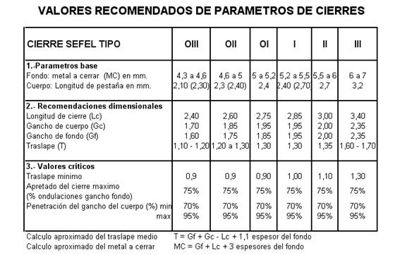
7º.- RECOMMENDED VALUES OF THE PARAMETERS OF THE FASTENERS
We have previously given some general guidelines for critical values, but these are not valid for all containers. Depending on their shape, these values can be more or less demanding. We have already discussed the case of non-round containers.
But what most influences the amounts of these values is the type of closing chosen. This type depends on the dimensions of the container and above all on the thickness and hardness of the metal used in the bottom and body. Later on, when we discuss the evolution of the fasteners, we will study in more detail how the characteristics of the metal influence the basic parameters (amount of metal to be fastened and flange). The critical values of the fasteners are defined on the basis of these dimensions.
Base parameters:
a.- The metal to be closed is defined as the area of the bottom that is incorporated into the container closure, i.e. its flange. Its approximate value is determined by the formula indicated at the bottom of the following summary table.
b.- The other basic parameter, or starting point for the fastener, is the flange length, which we have already defined in the fastener terminology.
SEFEL classifies fasteners into six different types or sizes, the first three of which fall into what we could call “mini fasteners” and the remaining three for conventional fasteners. There is a seventh type for large closures which is not included in the summary table.
The table reflects:
1º.- Types of SEFEL closures
2º.- Your starting or base parameters
3º.- The recommended magnitudes of the fundamental parameters of the closure itself.
4º.- The values of the critical parameters of the seals
5º.- The empirical formulas for the approximate determination of the:
o Closure overlap
o Metal to close from the bottom
8º.- DIMENSIONAL VARIATIONS OF THE CLOSURE
Small variations in closing are inevitable. These variations are mainly due to the following factors:
a.- The thickness of the metal used depends on the type and size of the container. In addition to the normal manufacturing tolerances of tinplate or TFS, there may be variation in the ductility and hardenability of the metal.
b.- The type of seamer used, as each machine has different characteristics, such as number of revolutions of the mandrel, diameter of the roller, closing speed, etc.
c.- Surface characteristics of tinplate or TFS. The presence of different types of varnish or lithography affects the behaviour of the metal during seal formation.
d.- Temperature at which the seal is made.
In order to minimize the effects these factors have on the sealing dimensions, strict discipline in the setting and adjustment of the seaming machine, as well as in its operation, is imperative.
9º.- INTERNAL DEFECTS IN A FASTENER CAUSED BY A BAD ADJUSTMENT OF THE ROLLERS AND ITS CAUSES.
We will start from the following hypotheses:
1º.- We assume that both the bottoms and the bodies – or containers – supplied to the seamer are correct.
2º.- The tools installed in the machine are suitable and in perfect condition.
Therefore, the defects that may appear during the closing operation can only be attributed to a bad adjustment of the equipment.
If the tools and components to be closed present problems, the range of possible causes opens wide. Therefore, when a defect occurs, the first thing we have to verify is that the bottoms, containers and tools are OK, and thus discard these factors and focus exclusively on the work of the adjustment.
1º.- FIRST CLOSING OPERATION
After the first closing operation, the ideal appearance of the section is similar to that shown in figure 48.
A.- If there has been an insufficient formation of body and bottom hooks, i.e. if the roller is too loose, as shown in figure nº 49, this can cause the following defects:
1.- Short bottom hook.
2.- Excessive length of the zip.
3.- Formation of folds in the bottom hook.
4.- Large body hook
5.- Small Solape
6.- Peaks at the base of the fastener
Defects 2 and 6 are easily seen without disassembling the seal and have been dealt with previously. Defects 1, 3, 4 and 5 require the closure to be opened for analysis.

B.- If excessive pressure is applied in the first operation, as shown in figure 50, this could cause the following defects in the seal:
1.- Short body hook.
2.- Excessively long bottom hook.
3.- Insufficient length of the fastener.
4.- Insufficient tightening of the lower part of the locking system.
Except for defect 3, the seal must be disassembled for detection.

2º.- SECOND CLOSING OPERATION
The analysis of the results obtained after applying the 2nd operation on a fastener cannot be simplified as much as in the case of the 1st operation (loose or tight pulley), since a series of adverse effects may occur, the origins of which may be various. For this reason we will do the analysis in reverse, we will start from the result to define the possible causes.
A.- Short body hook
If the locking section has a hook body that is too short, as shown in figure no. 51,

the causes of this defect can be in:
1.- Insufficient pressure in the compression plate.
2.- First operation pulleys too tight.
3.- Rulines of second operation not very tight.
4.- Incorrect height of closed adjustment, i.e. the chuck is too high in relation to the compression plate.
B.- Long body hook
If, on the other hand, the section of the fastener has a hook body that is too long, as shown in Figure 52, the causes in this case may be as follows:

1.- Too much pressure on the compression plate.
2.- Incorrect closed height adjustment.
3.- Rulines of 1st operation not very tight.
4.- Rulines of 2nd operation too tight.
C.- Short bottom hook
The section of the closure in this case is presented as in figure no. 53. Its probable causes are:
1.- Rulinas of first operation too little tightened.
2.- Too much pressure on the compression plate.
3.- Compression plate too high.
4.- Rulina of first operation high with respect to the mandrel.
5.- Rulina of second operation high with respect to the mandrel.

Figure No. 53: Short bottom hook
D.- Long bottom hook
See figure nº 54. Possible causes:
1.- First operation pulleys are too tight.

Figure no. 54: Long bottom hook
E.- Excessive length of the fastener
See figure nº 55. Most likely causes:
1.- Rulines of 1st operation too little tightened.
2.- Rulines of 2nd operation too tight.
3.- Rulina of first operation low with respect to the mandrel.
4.- Rulina of second operation low with respect to the mandrel.

Figure no. 55: Excessive length of closure
F.- Insufficient length of the fastener
See figure nº 56. Most likely causes:
1.- Rulines of 1st operation too tight
2.- Rulinas of 2nd operation too little tightened.
3.- Rulina of first operation high with respect to the mandrel.

Figure no. 56: Insufficient length of closure
10º.- CLASSIFICATION OF DEFECTS IN THE CLOSURE
Defects in the closure are not all of equal importance. According to the classic division of “critical”, “major” and “minor”, there are those that should always be included in only one of the categories, because they persistently have the same type of incidence, but there are also those that, depending on the magnitude in which they occur, can be included in two or even in all three categories.
Taking into account the different types of defects that we have seen so far, in general terms the following classification can be made:

11º.- CONTROL AND DIMENSIONAL ADJUSTMENT OF THE SEAMING MACHINES
The quality of the seal is a true reflection of the seamer’s ability to function properly.
It is easy to understand, particularly with irregular cans, that if for example the seaming rollers do not precisely follow the seaming mandrel, the degree of roller adjustment will not achieve perfect results. In the same way, if the bottom mandrel is not the right one, or the profiles of the locking rollers are not the optimal shape to control and form it, you will not get a good result in the dimensions.
Good seamer design allows the machine to produce consistent sealing quality, with minimal downtime to repair mechanical failures or make adjustments.
It is essential that the first operation is checked frequently, recording the height and width of the operation. This provides the information necessary to determine when to change the roller. Over the last few decades significant improvements have been made to locking tools, introducing corrosion resistant materials with surfaces that, due to their hardness, have a longer service life without the need for replacement. These improvements are to some extent linked to the introduction of thinner and harder packaging materials or even new ones such as TFS.
Certainly, the change from tinplate to tin-free steel (TFS) causes a dramatic reduction in the half-life of the roller that comes into contact with the chromic oxide coating on the bottom, compared to the much softer tinplate bottoms. Switching to TFS, however, improves cost-effectiveness; however, the cost of the tool is a significant part of the economics associated with the introduction of TFS.
If the seaming machines are properly maintained, and the seaming tools (mandrels and rollers) are in good condition, analysis of the seamer will only provide information that will confirm that the process is under control. To ensure that the seamers are not subject to continuous adjustment, a process called “target setting” has been universally introduced in the canning and metalworking industry, which ensures that the seaming is carried out correctly.
12º.- ADJUSTMENT FOR OBJECTIVES
Each seaming machine must be adjusted and regulated according to its particular specifications, depending on the type of bottoms/lids and bodies it is going to work with, metal gauges and container diameters or formats. In general, the following procedure should be followed.
1º.- Checking the mechanical condition of the seamer.
To start a target setting process, it is first necessary to establish the mechanical state of the seamer. For the sake of simplicity we will describe the setting of a multi-purpose seamer for cylindrical cans, of the rotary can type.
The first step to take is to determine the alignment between the mandrel chuck shaft and the compression chuck or lifter plate assembly. To do this, one of these compression plate assemblies must be removed from its support bearing. This alignment can now be accurately measured and recorded by placing a magnetically supported dial indicator on the spindle shaft. By raising and lowering the shaft of the compression plate, we will see the variation of the needle. In theory, the reading should be less than 0.005″ (0.16 mm), however it is only imperative to make an adjustment if it goes above 0.012″ (0.30 mm). Each machine has its own adjustment system, which can vary from the use of suitable wrenches to more complex systems. It is sometimes a difficult task, but to achieve a good quality seal alignment is essential.
Once alignment is established, the vertical and lateral clearance of the spindle shaft bearings should be measured and should be less than 0.002″ (0.05 mm). Excessive vertical clearance, for example 0.005″ (0.13 mm), will require further examination and replacement if necessary. The bearings and shafts of the locking rollers must then be examined for lateral and vertical clearance. Under no circumstances should values exceeding 0.002″ (0.05 mm) in lateral play and 0.005″ (0.13 mm) in vertical play be accepted.
Finally it is passed to the compression plates. To ensure a good quality of the closure, both the loss of parallelism and alignment with the mandrel and the excessive play with the flange, in the case of closing an empty container, as well as with the lid tray already in place, in the case of closing a full container, must be corrected.
Once you have established the good condition of the key points of the seamer, which determine the quality of the seam, you can start the target setting exercise.
2º.- Verification that the mandrels and rollers are suitable for the type of container to be closed.
The first objective is to check the seating between the mandrel and the bottom. It is useless to adjust the seamer accurately if the bottom fits too loosely or too tightly in the chuck. In the case of lids that are not of the easy-open type, a positive effort must be required to accommodate the bottom in the mandrel. See figure 57. The degree of interference between mandrel and bottom should be 0.10 mm. This value is very difficult to measure, but in principle, with the mandrel on the bottom, there should be a gap of 0.10 mm between the end of the mandrel lip radius and the trough depth of the bottom. So when the mandrel is pushed firmly on the bottom, and comes to rest on the base of the flask, it will overcome an interference of this value (0.10 mm). The design of the mandrel lip is a critical point to take care of for the sealing operation.

Figure no. 57: Mandrel seating on the bottom
The profiles of the rollers are a function of the type of closure to be used, which in turn is linked to the dimensions of the bottom flange, the body flange and the metal thicknesses used. They are also linked to the round or irregular shape of the packaging.
3º.- Prepare the machine for the closed height adjustment.
Assuming that the chuck to bottom fit is correct, the “Closed Fit Height” (Hc) must then be adjusted. This is the distance between the top face of the compression plate and the bottom face of the locking mandrel.
In order to carry out this task properly, it will be necessary to have the specifications of the supplier of containers and funds available.
The correct setting of the closing height on the seamer is important for two reasons:
– The correct dimensioning of the body hook in the latch depends on the correct height of the latch adjustment.
– In filling plants, the proper position of the body flange in relation to the steam flow change parts must be achieved and maintained.
The formula for calculating this dimension is
– Unsealed can height (M) minus chuck lip height (A) plus a constant taking a value of 0.043″ (1.09 mm)”.
Hc = M – A +1.09
The 0.043″ (1.09 mm) value represents the compression plate lift during the actuation cycle of the first closure operation, which is 0.022″ (0.56 mm), plus the reduction in package height during this cycle, which is 0.021″ (0.53 mm). The “closed setting height” must be measured during the first operation. See figure nº 58. The height gauge should be set when the cam follower of the first closing operation coincides with the peak or maximum point of the cam.

Figure no. 58: Adjusting the distance between the mandrel and the compression plate.
4º.- Adjust the pressure of the compression plate.
The next step is to adjust the force of the compression plate, i.e. the spring pressure of the plate. It is a factor that has a great influence on the formation of a correct seal. During the sealing cycle, and until it has been formed, the height of the can body is reduced in order to achieve the correct formation of the body hook and the bottom. To do this, it is necessary to exert constant and controlled pressure on the can body.
The compression plate load is related to the thickness of the can body material, i.e. the thicker the can body material, the higher the pressure should be. It is also linked to the size of the can. For a typical body thickness of 0.18 mm it can be set to a value of 200 pounds, with a deflection of 0.022″ (0.56 mm). See Figure 59.

Figure No. 59: Adjusting the compression plate
A special dynamometer is needed to adjust the compression plate to this preset load. Most seaming machine manufacturers offer this equipment in their catalogues, and provide information on the appropriate values of this pressure depending on the container to be sealed.
If during the final analysis of the closure, it is necessary to increase or decrease the length of the body hook to reach the desired targets, this should be done by increasing or decreasing the load and never altering the height of the closure setting.
In the article stability of the pressure of the compression plate on a seamer this task is developed in more detail.
5º.-Check the distances of the rollers in relation to the lip of the spindle.
Rulina of 1st operation:
When adjusting the first operation rollers, it is important to avoid direct, uncontrolled contact between the roller profile and the mandrel lip, as this profile could be damaged by the edge of the mandrel lip. To position the roller properly, this adjustment must be made when the top of the cam that controls the movement of the arm of these rollers is acting, that is to say, in its position of maximum approach to the mandrel.
Once on the first operation cam projection, the distance of the roller to the mandrel lip is first adjusted, for this purpose the thickness value of the 1st operation cam must be known, which must be indicated in the specifications of the fastener. Wire gauges or calibrated rods are used for adjustment.
The roller is then adjusted to the height of the roller in relation to the mandrel lip. This value is normally 0.003″(0.07 mm) for the 1st first operation above the mandrel lip. See figure nº 60.

Figure no. 60: Height adjustment of locking rollers
Precise adjustment of these heights can be achieved with the aid of a set of feeler gauges. For non-round containers, this roller should be adjusted as low as possible to avoid laminations at the top of the closure.
One way to simplify the height adjustment of the rollers in relation to the mandrel is to use “double guide” guide carriages. In them, a channel is made that adjusts to a heel or protrusion that presents the upper part of the mandrel. See figure nº 61.

Figure No. 61: Double guide pulley
In this way, the 1st operation roller, which tends to rise during its work, will stop against the lower face of the mandrel heel. The 2nd operation roller presents the opposite case.
Rulina of 2nd operation:
The same procedure as described for the 1st operation roller is repeated for the 2nd operation roller. Adjustment is also made at the top of the 2nd operation cam.
The height in relation to the top edge of the mandrel lip in this case is 0.005″ (0.13 mm) See Figure #60. In the case of non-round containers, this roller must be set somewhat higher than in the case of cylindrical containers.
6º.- Verify the closing pressures of the rollers and final adjustments.
Once the adjustment of the first operation is finished, the machine can be operated with cans and bottoms, measuring the dimensions of this operation and analyzing its cross sections. If correct, the procedure is repeated for the second operation rollers. If this is not the case, the roller pressure setting must be checked again. The resulting cell depth after closing must also be checked.
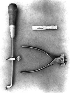
In this way the closure is ready for evaluation, either by the “scrapping” method or by projection of its section, as mentioned above. See figure nº 62.

Figure No. 62: Methods of closure assessment
7º.- Ejectors
This subject has already been dealt with in the section “Closing operation” – “Basic parts of the tooling”.
– Click here to access the 4th part of this work.
Back to Double Seaming Mundolatas
 Theoretical calculation of the volume of rubber required for the closure of a metal container.
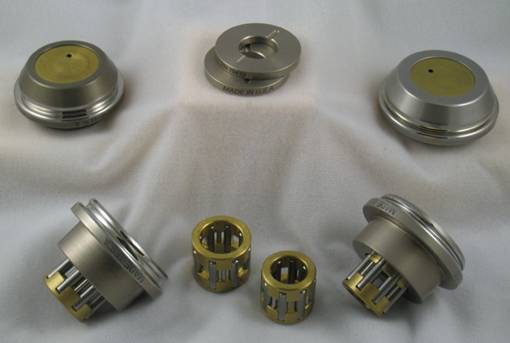
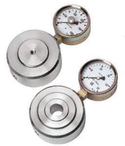
 Double closure measuring equipment
 ROLLERS 2ND CLOSING OPERATION
 CLOSURE THEORY – Part 4
 CLOSURE THEORY – Part 2
 CLOSURE THEORY – Part 1
 DOUBLE SEALING OF RECTANGULAR CONTAINERS
 STABILITY OF THE PRESSURE OF THE COMPRESSION PLATE IN A SEAMER
 ELEMENTS OF THE DOUBLE SEAL
 MEASUREMENTS OF THE DOUBLE LOCK


0 Comments