This is the beginning of a work on the
THEORY OF CLOSURE
which is published in four parts or chapters.
PART 1: INDEX
1º.- INTRODUCTION
2º.- TERMINOLOGY
A.- Body of the container
B.- Bottom of the container
C.- Terminology of the closure itself
D.- Seamer tools
3º.- GENERATION OF THE CLOSING:
– Rulinas
– Compression,
– 1st operation,
– 2nd operation,
– Sealing of the closure
– Critical parameters.
4º.- CLOSING OPERATION:
– Closing machines:
– Cylindrical can seamers
– Irregular can seamers.
– Basic parts of the closing tooling
– Rulinas:
– 1st operation
– 2nd operation
– Mandrill
– Compression chuck
– Ejector
-Closures:
– Closure of cylindrical cans
– Closing of irregular cans.
5º.- EVALUATION OF THE CLOSING:
– Preparation.
– Execution
1st Phase:
– A .- Visual inspection
– B.- External measurements:
– Measuring the depth of the cuvette.
– Measuring the closing length
– Measurement of the fall in the joint
– Measuring the thickness of the seal Compacity
2nd Phase: Disassembly of the seal
– Center bottom panel cutout
– Cutting of a section of the closure
– Disassembly of the seal
– Preparation of the closure for projection
3rd Phase: Internal measurements
– Body and bottom metal thickness measurements
– Determination of free space
– Hook measurement
– Body hook penetration and overlapping
– Checking for internal seal defects.
4th Phase: Leaks
– Leak detection
6º.- ACCEPTABILITY OF THE CLOSING (Critical parameters):
– Tightening of the fastener.
– Body hook penetration.
– Overlap.
– Absence of visual defects.
7º.-RECOMMENDED VALUES OF THE PARAMETERS OF THE FASTENERS
8º.- DIMENSIONAL VARIATIONS OF THE CLOSURE
9º.- INTERNAL DEFECTS IN A FASTENER CAUSED BY A BAD ADJUSTMENT OF THE ROLLERS AND ITS CAUSES:
– 1st closing operation.
– 2nd closing operation:
– Short body hook
– Long body hook
– Short bottom hook
– Long bottom hook
– Excessive seal length
– Insufficient seal length
10º.- CLASSIFICATION OF DEFECTS IN THE CLOSURE
11º.- CONTROL AND DIMENSIONAL ADJUSTMENT OF THE SEAMING MACHINES
12º.- ADJUSTMENT BY OBJECTIVES:
– 1º.- Checking the mechanical condition of the seaming machine
– 2º.- Verification that the mandrels and rollers are suitable for the type of container to be closed.
– 3º .- Prepare the machine for the closed height adjustment.
– 4º .- Adjust the pressure of the compression plate.
– 5º .-Check the height of the rollers in relation to the chuck lip
– 6º- Verify the closing pressures of the rollers and final adjustments.
– 7º .-Expellers
13º.- ANALYSIS OF THE CLOSINGS
14º.- SEAMER MAINTENANCE PROTOCOLS
15º.- TECHNICAL IMPROVEMENTS AND EVOLUTION OF THE CLOSURE (MINI CLOSURES)
– Introduction
– Evolution of the closing
– First operation
– Second operation
– Evaluation of the “mini closing”.
– Critical parameters in the mini-closure:
– Tightening of the fastener
– Tightness Indicators
– Solape
– Body hook penetration
– Influence of the eyelash.
– Changes in the production line
16º.- PROGRESS IN THE TOOLING OF SEAMING MACHINES
17º.- SUMMARY OF DEFECTS IN THE CLOSING:
– ORIGIN AND EFFECT
– FAILURES AND THEIR CAUSES
18º.- SIPSONIS
19º.-EQUIVALENCES OF TERMS OF THE CLOSURE: ENGLISH – SPANISH
20º.- BIBLIOGRAPHY
CLOSURE THEORY
1º.- INTRODUCTION
We intend with this work to present in a clear and detailed way, both to container manufacturers and packers, the basics of the theory of closure, so that they can know in depth the features and
types of closures for metal cans
.
Careful reading of this work will help to control the quality of the seals, as well as to regulate the sealing machines. The main objective is to assist decision makers and determine the quality of the closing. Whether a production line will continue to operate or whether it will have to stop depends on the judgement of these people.
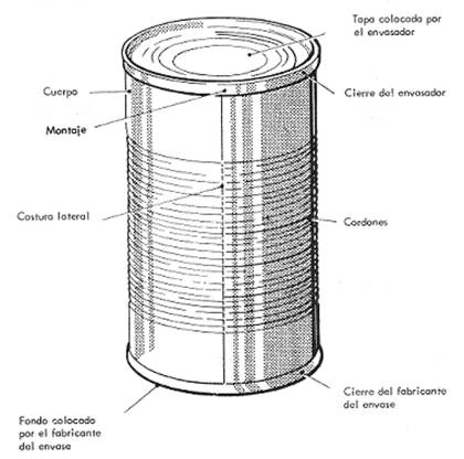
Let’s start by identifying the different parts that make up a container. Figure nº 1 shows a metallic can and its different elements are written on it.
Figure 1: Elements of a metal can
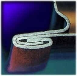
It is defined as “seaming” or “double seaming”.the result of joining the end of the body of a container with its bottom or lid. The seal is obtained by curving the bottom flange around the body flange, hooking them together to produce a hermetic joint. This joint therefore uses a double crimping technique, i.e. it generates a double security wall. Its objective is to obtain a completely watertight joint.
Good sealing is an essential condition, necessary but not sufficient, to avoid bacteriological contamination, corrosion and alteration of the product. It must have sufficient mechanical characteristics to withstand, under normal conditions, the filling, handling, transport and storage process.
It is carried out on equipment called seaming machines. These machines come in a wide variety of designs and capacities, from the simplest, hand operated, to the most complex, automatic machines at high production speeds.
In this document we will present how the closure is generated, the elements that compose it and the tools that make it, as well as the main problems that may arise during its execution. We will also analyse the different designs and sizes of the closures, recommended according to the diameters and characteristics of the containers used.
For the uninitiated reader, we suggest that you start by reading first the TERMINOLOGY of the closure, which follows, so that you can easily follow the lexicon used throughout this work. The reader with prior knowledge of this subject can skip it and move on to the next point.
2º.- TERMINOLOGY
Below we define the different technical terms used in closure theory. Let’s start by listing the parts of the container body and bottom that will be involved in making the closure.
A.- Body of the container
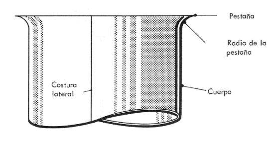
Figure nº 2 shows the following elements
– Lateral seam: Lateral union of the container body, normally achieved by electric welding, although it can also be achieved by a process of seaming with the contribution of a
thermoplastic sealing cement
.
– Body: Cylindrical, rectangular or irregular part that forms the walls of the container.
– Flange: flange that the body has at each of its ends. It consists of a flat part, almost perpendicular to the wall of the container body, and an arc joining this flat part to the container body.
– Flange radius: Radius of the arc of the flange and that joins it to the body.
Figure 2: Elements of the can body that are part of the closure
B.- Bottom of the container:
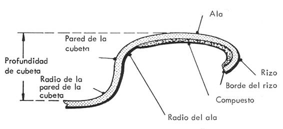
Figure nº 3 shows the components of the bottom that participate in the closure.
– Bottom flange: Outer portion of the bottom that deforms during the closing operation and becomes part of the closure.
– Curl edge: end part of the curl. There is always exposed steel in it, which makes it sensitive to rust.
– Sealing compound (or rubber): Substance formulated from synthetic rubbers, which facilitates the hermetic sealing of the closure. It is applied on the inner part of the bottom wing.
– Trough wall: Side wall delimiting the bottom cavity, which houses the closing mandrel.
– (e) Distance from the top of the flange (in the case of loose bottom), or from the closure (after closure) to the centre panel of the bottom. It should be measured at the point where the radius of the bottom trough ends.
– Bowl wall radius: Arch that connects the bottom of the bowl wall to the center bottom panel.
– Flange radius: The arc that connects the top of the trough wall to the flange.
– Curl: Inward curvature of the end of the bottom wing. During closing, it serves to initiate the formation of the bottom hook.
Figure no. 3: Components of the closing fund
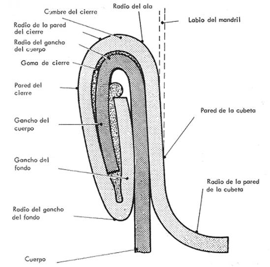
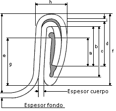
C.- Terminology of the closure itself : It is shown in drawings nº 4 and 5. . Those elements of the closure that are physical magnitudes – length measurements – are shown in drawing no. 5, dimensioned by means of a letter.
Mandrel Adjustment: Determines the degree of adequacy of the positioning and penetration effort of the mandrel inside the bottom trough.
Wrinkles in the hooks: These are undulations or folds formed vertically in the bottom hook. They are undesirable, because if they have a certain importance, they can affect the tightness of the seal.
– Cutting edge: Sharp protrusion located at the junction between the top of the closure and the trough wall.
– Acute edge: A cutting edge to a lesser degree, no sharp edge but simply a right angle.
– Sagging at the joint: Downward deformation of the bottom hook in the area of the side weld.
– Closure: It is the part of the can formed by the union of the edges of the bottom and the body, by means of hooks or folds that interlock and form a structure of high mechanical resistance. It has to be airtight.
– Compacity: Ratio between the five metal thicknesses of the fastener and the actual thickness of the fastener expressed in %.
– Summit of the clasp: Rounded upper area of the clasp. It is a part of the bottom wing already deformed.
– Free space: It is the difference between the thickness of the seal actually measured and the sum of the thicknesses of the five sheets that are included in the seal.
– Thickness of the closure: (h) Maximum dimension of the closure measured perpendicular to the axis of the container. It contains the five metal layers of the clasp.
– False fastener: Area in which some sections of the hooks of the fastener are not agrafados, although the appearance is of a normal fastener.
Figure 4: Closure terminology
– Body hook: (d) Portion of the body flange that bends downward during closure formation.
– Bottom hook: (g) Part of the bottom flange that folds up during closing to engage with the body hook.
– Gap: (i) The empty space between the inner part of the top of the clasp and the upper area of the body hook.
– Gaps: Open spaces located at the end of the phono hook and body that are filled by the compound during the closure operation.
– Mandrel track: Marks left by the mandrel around the inner periphery of the body contiguous to the radius of the cuvette wall, formed by the pressure applied by the closing rollers during the closing process.
– Closure length: (f) Distance between the summit and the base of the closure.
– Critical parameters: Values of the double seam that must be satisfied to achieve acceptability.
– Closure wall: Outermost part of the closure, formed by the outer face of the bottom hook. It has the shape of the profile of the second operation roller, i.e. with a wide radius curve.
– Slippage: Incomplete formation of the seal, due to a displacement of the roller in the second operation.
– Body hook penetration: (b/c) Ratio between the length of the body hook and the internal length of the fastener, expressed as a percentage. Indicates the amount of the body hook that has been driven into the bottom compound or joint.
– Peak in the assembly: Angled projection located at the base of the fastener in the area of the side seam
– Bottom hook pressure (or tightness): Height of the corrugations present on the bottom hook, measured in % of the hook height.
– Closure wall radius: Curve that connects the top of the closure to the wall of the closure.
– Body hook radius: Bending curve in the formation of the body hook.
– Bottom hook radius: Plunging curve at bottom hook formation.
– Primary seal: The seal produced when the body hook is driven into the rubber or compound gasket housed in the bottom hook.
– Secondary seal: The seal created by overlapping and crushing of the body hook and the bottom hook inside the closure.
– Overlap: (a) The amount of overlap generated at the closure between the body hook and the bottom hook.
As we have already said above, those elements of the closure that are physical magnitudes – length measurements – are shown in drawing no. 5, which appears below, delimited by means of a letter.
Figure no. 5: Dimensions of the measurable parts of a fastener.
– Joining or assembly: Part of the fastener coinciding with the side seam of the body.
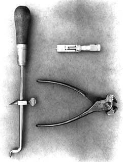
D.- Seamer tooling:
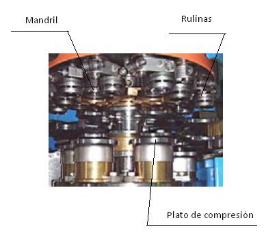
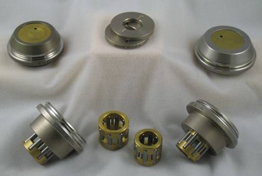
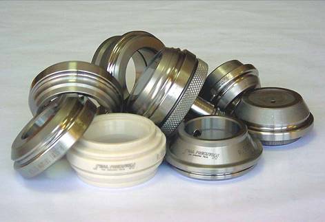
The parts of the seamer that are directly linked to the seamer are the seamer tools. These pieces change depending on the size of the container and the type of closure we want to make. In the photo nº 6 you can see some of them. We define them and their main settings:
– Closing adjustment height: The distance between the bottom face of the closing mandrel and the top face of the compression plate. This distance is measured when the top of the cam of the first operation is actuated.
– Compression plate base load: Force applied to the base of the can, through the compression plate, during closure formation.
– Closing machine: Machine that performs the closing operation between the bottom and the body. It also goes by other names such as sertidora.
– Ejector: Part of the seamer located in the center of the mandrel, which pushes the closed container to extract it, once the second operation has been completed. It has height and force regulation
– Mandrel lip: Edge of the mandrel chuck in contact with the cuvette wall.
– Mandrel: Part of the seamer tooling that changes with the diameter of the container. It lodges in the bottom trough during the formation of the seal. It acts as an anvil against which the clasp is formed.
Picture No. 6: Tooling of the seamer heads
– Profile of the roll: It is the necessary contour of the active part of the roll to achieve the correct metal forming, which is required to meet the specifications of the body and bottom hooks.
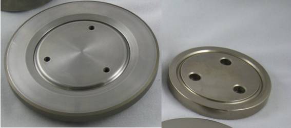
– Compression plate: Part of the seamer tooling that changes with the diameter of the container. The can sits on it during the formation of the closure. It is equipped with up and down movement and acts spring loaded. It is also called “base dish”.
– Rulina : It is the part of the seamer that performs the operation of deforming the metal, to configure the hooks of body and bottom and the link between them. There are two types, first operation, which forms the hooks and binds them together, and second operation, which crushes them together. It is also known by other names such as: trolleys, locking wheels, locking wheels, locking rollers…
3º.- GENERATION OF THE CLOSING
Another way of defining “closure” is: “the airtight seal made between the body of the can and its bottom”. This is a metal deformation process, which basically consists of two operations, although in cases of difficult irregularly shaped container closures, three operations may be necessary. To achieve watertightness, it is necessary to use a rubber – or compound -, which is deposited on the internal part of the bottom flange, and after the closing operation has been carried out, it is placed inside the seal.
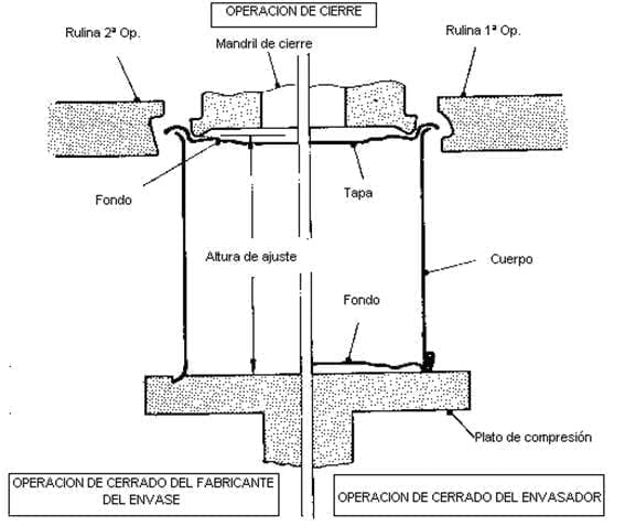
Closing is carried out as shown schematically in figure 7, and is basically broken down into 3 successive steps:
- location or positioning of the base in position on the body and the container body on the compression plate
- first closing operation
- second closing operation
Figure no. 7: Schematic diagram of the closing operation
Rulinas:
The closing is carried out by the action of two rollers or closing rollers, which are also called by different names depending on the geographical area (wheelbarrows, wheels, wheels, rollers…). Their work is divided into a first operation, followed by a second.
They have a throat, or working area, formed with special shaped silhouettes, called “closing profiles”. This profile is of variable shape depending on whether it is a first or second operation, depending on the characteristics or specifications of the flange or bottom closure panel of the can, and the thickness of the material to be sealed. As a general rule, the larger the size of the bottom flange and the thicker the material, the wider and deeper the profile of the roller, i.e. it is a function of the container format and the gauge of the metal used in its components. This means that the same type of profile can be used, but its dimensions increase or decrease depending on the size of the container and the metal thicknesses.
Between the first and second operation locking rollers, the main difference is in their profile and mission, since the first operation trolley’s main purpose is to wind the bottom flange around the hook of the body, while forming the body. The purpose of the second operation trolley is to tighten and iron the seal already started, in order to make it airtight. Let’s take a closer look at these three steps of closing.
Compression:
The container to be closed – body and bottom – is placed on an adjustable plate, which can be moved vertically, so that the container is retained between this plate and the closing mandrel.
The compression is carried out by means of a spring, and its main mission is to avoid the relative movement of the container with respect to the closing mandrel, allowing the progressive transformation of the body flange and bottom flange during closing.
First operation:
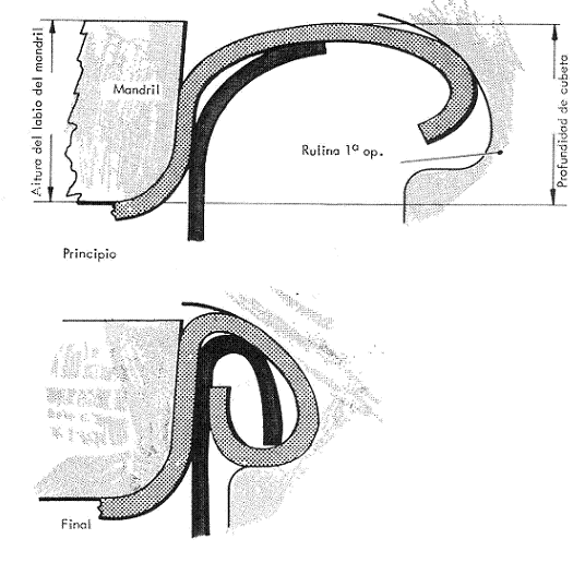
As we have already indicated, during the first closing operation, the bottom flange is gently rolled over the flange of the can body, at the same time that the latter is folded, forming very loose hooks, leaving space between its walls. The beginning and end of this step is represented in two sequences in the drawing nº 8.
Figure no. 8: Beginning and end of a first closing operation
As can be easily seen, the correct performance of this first operation is decisive for obtaining a good seal, and special care must be taken in its adjustment.
A cross section of the first operation should show a good overlap of the hooks or folds of the body and the bottom, and also the absence of distortions in the formation of the joint. The cuvette depth increases slightly and gradually during the first and second operations.
Some details of closure formation during the first operation of irregularly shaped bodies and bottoms will be given later; however, the principles of acceptability are the same for both cylindrical and irregularly shaped cans.
Second operation:
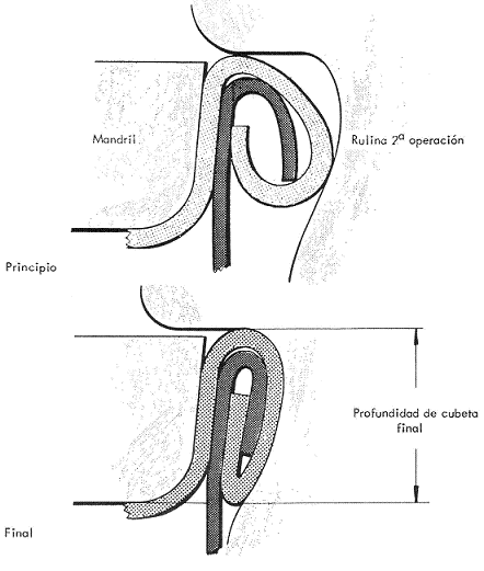
Once the first seaming operation is completed, a second forming roller is used to compress the five metal layers (two on the can body and three on the bottom) to form an airtight seam. The operation of tightening and ironing the bottom and body hooks together is carried out progressively. Figure 9 also shows the beginning and end of this step. This operation gives the closure sufficient mechanical strength and watertightness to withstand with guarantees, and under normal conditions of use, the various stages of the manufacturing and distribution process of the packaging.
Figure no. 9: Beginning and end of a second closing operation
Sealing of the closure:
Two sealing zones can be identified on the closure. The seal is first produced by pinning the edge of the can body, i.e. the body hook, against the rubber or composite gasket, the scuffing material that lies within the fold formed in the bottom flange, or bottom hook. The secondary seal is created by the overlapping and crushing of the body hook and the bottom hook, on the inside of the seal.
The volume, type and weight of the sealing rubber changes notably with the diameter of the containers, varying its composition according to the product to be contained in the container. A lack of compatibility between the sealing compound and the contents of the container can lead to contamination of the product and the rubber, significantly impairing the characteristics of the closure.
The application of this sealing compound
The application of this sealing compound is carried out by means of
The application of this sealing compound, which can be carried out by different techniques: tampon, shower or nozzle. Its regulation at the time of application must be done with extreme caution to avoid leakage problems in the container. The purpose of the composite is to occupy the free space and existing gaps within the enclosure.
The seal thus obtained must have an appropriate mechanical resistance and sufficient watertightness under normal conditions of use.
Critical parameters of the closure:
The main aspects or factors in the formation of the seal, which produce a leak-free joint, are called critical acceptability parameters and are as follows:
– Tightness of the seal: Shows the degree of tightness. Ensures that the double seam is under sufficient pressure.
– Body hook penetration: Reflects the recess of the body hook within the net height of the closure. Measures the formation of the primary seal.
– Overlap: The overlapping of the two hooks (body and bottom). Measures the formation of the secondary seal.
We will return to these concepts in greater depth later.
4º.- CLOSING OPERATION
A.- CLOSERS
The sealing operation of canned food containers or any other product, are carried out in the
can seaming machines for containers or cans
. In principle, they can be classified into two main groups: Cylindrical can seamers and irregular can seamers.
Cylindrical can seamers
Most of the cans are cylindrical. Higher filling and closing speeds can be achieved more easily with this shape. The seaming machines working with cylindrical canister are divided into two types:
-1º.- Those in which the container rotates during the closing operation. They can have one or several heads and allow high closing speeds. In these machines, the container and its lid, which are fed separately to the machine, are placed between the mandrel and the compression plate, the ejector keeping the lid in place while the plate goes up until the container is in the closing position, pressed against the mandrel. At that moment, the compression plate, the container and the mandrel start to rotate together, producing the first closing operation by the action of the corresponding rollers, which are approaching carried on their arms and driven by a cam; then, by an analogous procedure, the second operation is carried out, the same plate and the closing operation is finished.
They are used for the manufacture of cans and also in the filling of certain products. To establish the closing speed of a machine, factors such as: diameter of the container, product to be packed and possibilities of product spillage must be taken into account.
– 2º.- Those that keep the can without rotating during the seaming process. In this type of seaming machine the can remains motionless, while the seaming head of the machine rotates around the can. In this head are housed the roll-holding arms.
There are also variants of this type of vacuum sealing machines that work under vacuum for specific products such as meat, dairy products, etc. There are several ways to achieve a vacuum in the filling and closing process of a container:
– Mechanical vacuum, by means of a vacuum pump, keeping the container in a hermetically sealed chamber during sealing.
– Steam vacuum, expels air by injecting a jet of steam into the headspace of the filled container. When the vapour condenses, a vacuum is produced.
– Vacuum by hot filling, achieved by filling the container to the top of the hot product and therefore dilated, when it cools and reduces its volume generates a vacuum chamber inside.
Depending on the product to be packaged, one type or another of seamer is chosen, so the first case is used for dietetic products, and the last one for meat products. The use of vacuum always reduces the cycle speed.
Irregular can seamers
The term irregular covers all types of cans that are not cylindrical. These seamers are designed for seaming oblong, oval, rectangular, square, or pear-shaped cans; they usually operate at low speeds and have a complex design. Some of these seaming machines are designed to operate under vacuum, which further complicates the mechanical operation of the equipment.
The principle of operation is as follows: the cans filled with product reach the machine, either manually or mechanically, up to the seaming platform, commonly referred to as the “compression plate”, before the bottom is positioned on the can. The container and base are therefore positioned in the same way as with a round container sealer.
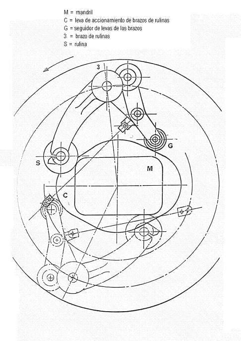
In these machines, the rollers of the first operation, which are usually a pair, are placed diametrically opposite each other. They rotate around the mandrel and the container, which are stationary, exerting a certain pressure on the latter, which is regulated by the action of a cam. See drawing nº 10.
Figure no. 10: Plan view of a closing head for rectangular containers
Then, in a similar way, the second operation rollers come into action. Once the closure is finished and the second operation arms are separated, the ejector acts, separating the container from the mandrel, accompanying the compression plate in its lowering movement.
Some vacuum irregular can seamers, fed by hand, lift the can in two stages. This means that once the can has been placed on the plate, the mechanical movement of the machine lifts the can to a point below the seaming roller. In this position the vacuum is created in the closing chamber. This vacuum triggers the second lifting motion, which raises the can to allow the start of the seaming operation. Higher speed seamers normally operate with a pre-vacuum station prior to seaming.
Some types of rotary starwheels allow to increase the speed, but rarely exceed 100 cans/minute. When it is not possible to maintain a separation between the body and its bottom before the start of the seaming operation, during the time that the vacuum is made, then it is necessary to use specially designed bottoms, which provide a passage for the air to escape from the inside of the can. This is achieved by making notches on the bottom flange, which rest on the flange of the body, slightly raising the level of the wing, and thus leaving a free space for the exit of the interior air. Without this separation, the can body flange would snap over the bottom flange rubber, creating a seal that would prevent vacuum from being achieved inside the can. This special type of background is often referred to as a “dimple” background. We will come back to the complexity of closing irregular containers later on.
Basic parts of the locking tool
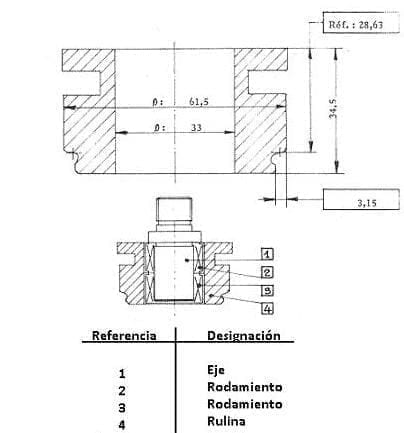
Rulines: These are steel rollers in the case of container manufacturers or special stainless steel for canners, with a very high degree of hardness. They are mounted on a shaft or on bearings. See figure nº 11
Figure no. 11: Rulina closing
The roller shown here is of the double guide type, and the assembly of its shaft with the corresponding bearings can be seen. The dimensions shown on the drawing refer to the dimensions suitable for a specific type of seamer – FMC. 521 -. The dimensions enclosed in a rectangle are basic for a correct fit, as they mark the distances from the reference point in the throat of the truck to its heel (3.15 mm), and to its guiding surface (28.63 mm).
The working areas of these rollers are configured with specially shaped silhouettes, called “closing profiles”. The arm where they are inserted, performs a movement of approach and separation with respect to the mandrel in an automatic way. This movement is controlled by a cam.
Their mission during the closure, and their performance during the closure have already been described above. The shape and dimensions of the roll profiles have a decisive influence on the tightness of the seal. The grooves of the rollers must have an excellent surface finish. The better the surface finish, the better the results will be.
Rulina of first operation: Its profile is always deep and narrow, being the curvature of the lower edge more pronounced than the upper one. See figure nº 8. The profile acts as a generatrix to form the hooks of the body and bottom. Its purpose is to roll up the metal of the bottom flange with that of the body flange, the latter being inserted into the former. See figure nº 8. The resulting fastener has a rounded outer shape and is lower in height than the finished fastener.
Second Operation Rulina: Its profile is shallower and higher than that of the first operation, presenting a more accentuated curvature on its upper edge. See figure nº 9. As already explained, perform the finishing operation by pressing the fastener, formed in the first operation, against the mandrel, so that the hooks are flat and straight. See figure nº 9.
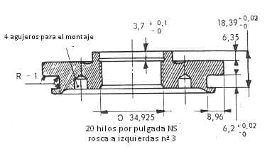
Mandrel: It is a plate mounted on a shaft, with a flange or lip that fits the bottom to be closed, and whose characteristics depend on the container manufacturer. See figure nº 12. Its dimensions also influence the shape and configuration of the closure, as it acts as a support base for the action of the rollers.
The mandrel shown in section in figure 12 is a typical example of a round container chuck, to be used with guided type rollers. It has a left-handed, fine pitch central thread to ensure that it does not loosen when turned clockwise. It is equipped with four holes on its lower face, for a special key for assembly and disassembly. On the same side there is a recess for the bottom profile.
Figure no. 12: Example of a round bottom chuck
The lip is slightly conical in shape to facilitate the ejection of the closed container and to better adapt to the initial shape of the flask. In the past, the lip surface was grooved to prevent the bottom from slipping during closing, but this practice has been eliminated because it caused damage to the protective varnish on the outside of the bottom, which subsequently led to oxidation in the area. Its central part is hollowed out, which serves to save the expansion rings and steps of the profile of the bottom panel.
The lip of the mandrel is defined by four basic dimensions which are shown in figure nº. 13
Figure N°13 : Profile of the lip of a mandrel
These are
– Lip height S1. The value of S1 is linked to the cell depth (A) of the bottom. SEFEL proposes the following formula for its determination:
or S1 = A + 0.13 for all round bottoms equal to or larger than 60 mm in diameter.
or S1 = A + 10 for diameters less than 60 mm.
– Lip inclination angle: Its normal value is 4º. Amount admitted by SEFEL
– Radius of the base of the lip P1 . Its normal value is 1 mm. Amount admitted by SEFEL.
– Diameter at reference point N2: The diameter N2 is obtained from the diameter of the bottom punch block (B1), i.e. from the part that defines the diameter of the bottom trough. SEFEL recommends the following formula :
N2 = B1 + 0.12
Compression plate:
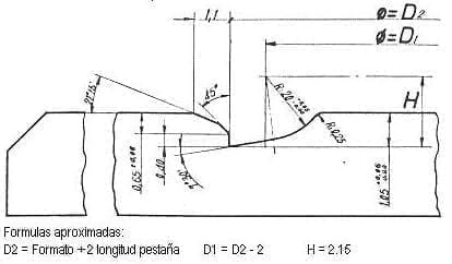
As previously mentioned, it serves as a support for the container, centering it and transmitting the pressure of the spring on the mandrel. Its shape depends on the shape of the end of the container. In the case of can seamers for can production, it has a profile copying that of the flange of the container body; for filling seamers, it has channels on its surface, which coincide with the closure of its base, to fix the can in the correct position. See figure nº 14. It presents the profile of a seamer plate for container manufacturing, and gives the approximate formulas for the determination of its measures, depending on the format to be closed.
Figure no. 14: Profile of the compression plate for the seamer of container manufacturers
It is mounted on a shaft. At rest it is at a greater distance from the mandrel than the container with the bottom positioned at the time of closing. The pressure is regulated by acting on this plate, we will come back to this later when we discuss the adjustment of a seamer.
The centering of the chuck also has an influence during closing. It must be perfectly centered with respect to the shaft and as parallel as possible to the chuck.
Ejector:
All automatic closing machines are equipped with ejection mechanisms, which at the same time help to maintain the correct position of the bottom on the container before reaching the closing position. In addition, the ejector separates the closed container from the mandrel, once the closure has been made.
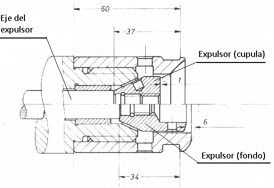
This ejector is a spring-loaded shaft with a small plate at its end, which is housed in a hole made in the centre of the chuck. It is equipped with a reciprocating movement (ascending-descending) acting in the centre of the bottom. See figure nº 15
Figure no. 15: Closing head for aerosol domes and aerosol bottoms with ejector
The head shown in figure nº 15 is that of a horizontal head seamer for the closing of domes and bottoms for aerosol cans. The upper part of the drawing shows the section of a dome head, in this case the extractor is shorter to leave space for the greater height of the dome. The bottom of the drawing shows the case of bottoms, which have a concave shape.
On seaming machines equipped with steam injection to achieve vacuum, a complete synchronization of the movements of the compression plate and the ejector is necessary. As the speed increases, the ejector setting becomes more critical, and must be more accurate the faster you work.
B.- CLOSINGS
Cylindrical can seals
Today’s can seamers for cylindrical containers, both stationary and rotary, produce uniform, high quality closures with few problems in terms of metal forming. However, the changes that have been introduced in the thickness of the bottom material, with significant reductions in thickness, have forced a redesign of the bottom flange in order to maintain a high quality of the seal. We will come back to this later.
The very frequent use of stuffed packaging in different sectors, such as fish and meat, has significantly reduced the risk of lack of quality in the closure, which would be reflected in alterations due to leakage. When using three-piece cans with electrically welded side seams, there is always an area of lower quality in the overlap of the bottom and body hooks, coinciding with the side seam region, due to an increase in the thickness of the body hook caused by the welding. This effect is accentuated to an extent that can be dangerous in the case of containers with a crimped – or crimped – side seam with the use of thermoplastic cement as a sealing material. Of course, the limitations on the use of this type of packaging for unprocessed products substantially reduce the risk of leakage. In any case, the closure acceptability standards applied must ensure that adequate integrity is maintained in that high-risk area of the seam.
If we compare the quality of the closure now achieved, with the generalised use of three-piece electrically welded or deep-drawn containers, with those formerly obtained with crimped containers welded with tin-lead solder, the results have improved significantly, as the closure remains uniform around the entire perimeter, without presenting high-risk areas, although there is always a point of lower quality in the area of the electrically welded seam, as we have already indicated.
Irregular can seams
There are a number of markets that use irregular shaped cans, such as: meat, fish and edible oils. However, the need to achieve high quality seams is more difficult when using these cans with irregular bodies and bottoms compared to the results achieved with cylindrical cans.
This will be better understood if we remember again how these cans are sealed. Once the bottom has been deposited on the body of the container, the whole assembly is placed on the compression plate. This lifts it up and lodges the bottom trough in the locking mandrel plate. The arms carrying the closing rollers start their inward movement – remember that there is normally a diametrically opposite pair of rollers for each operation – and contact the bottom flange. Once this contact is made, the metal deformation operation begins. The rollers of the first operation move progressively inwards as the can is turned over. The deforming operation creates a metal wave in front of the roller profile by the action of the roller. In cylindrical cans this wave is evenly distributed during the cycle of the first seaming operation. In irregular cans this forming operation works in the same way, except that as the roller of the first operation goes around the can, the wave of material that runs in front of the can when it reaches each corner is deposited on it. This lack of metal control at the corners often results in folds and wrinkles in the bottom hook of the first closing operation.
When the cycle of the second sealing operation begins, again normally by means of two roller arms, the joint is compressed to produce a tight seal with the aid of the rubber gasket, the gasket being held under sufficient pressure to produce a leak-free seal. Logically, the smaller the radius of the irregular can corner, the greater the risk of strong wrinkles forming and falsifying the seal. Various methods are used to reduce the risk of creases and wrinkles in the corners. Background design plays a crucial role in solving these problems.
If the bottom flange material is reduced at each corner, the metal wave that is deposited at this point during the first closing operation will be reduced in size. This produces a more uniform bottom hook on the straight sides and corners. Obviously, it is necessary to define some minimum critical parameters, and from them calculate the reduction in width of the flange, in order to balance the material that will be deposited in each corner during the closure. For further information, we recommend reading the work:
– Rectangular container closures
Machine manufacturers, in conjunction with metallographers, have studied the design of seaming operations to properly control the material in the corners of irregular cans. The reduction of wing material at the radii is done progressively, starting before the end of the straight section of the wing. First operation reels also usually start their curved movement gradually, a little before the end of the straight side, and before reaching the radius of the can. This allows for better control of the hook formation on the spokes.
Another way to improve the closure is that the first operation of the same, is made in two turns around the can instead of one and a fraction, as occurs in the round containers. This allows the metal of the wing to be shaped more smoothly and progressively, thus reducing the risk of creases and wrinkles.
– By clicking here you can access the 2nd part of this work.
Back to Double Seaming Mundolatas










I need a job in your organisation.
I had 42 yrs of experience in making the two aluminum can and worked on sealers
Worked for Reynolds Metals Hawaii and was taken over by Ball Corporation