lRESUMEN
The closing operation in a rectangular container has some characteristics that make it different from a round one, as it presents a higher degree of complexity. The following study explains this complication and gives guidelines for resolving it.
BACKGROUND
The closing operation consists of solidly joining the bottom or lid to the body of the container. This is achieved by crimping the edge of the lid – called the “flange” – to the edge of the body – called the “flange”. The basic tools of the fastener are:
– Mandrel: Plate that is housed in the lid trough and serves as a firm support for the operation.
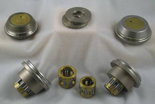
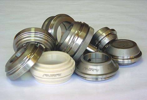
– Closing rollers: Rollers equipped with a groove with a special profile for each case. There are two types of rollers, first and second operation. The first ones, have the mission of curving and rolling the edge or wing of the lid over the flange of the body, thus initiating the seaming. The second ones, solidly crush the whole. These rollers are called by different names, depending on the type of pulleys and their areas: wheelbarrows, rollers, rollers, slices, etc.
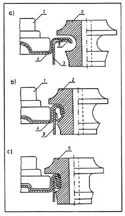
Figure 1 shows a schematic representation of the development of a fastener. In it 1) indicates the closing mandrel, 2) first operation roller, 3 ) container body, 4) lid. 5) second operation roller and 6) area to be closed: flange and flange.
The sequence a) is the starting position, b) is the actuation of the first operation roller and c) the second operation roller.
Figure 1: Sequence of a closure
For more details on the technique of a good closure we recommend reading the following works published on this website:
– “Closure measures“
– “Beverage container closure specifications“.
It is not the purpose of this article to go into more general questions about closures, we will focus on the particular case of non-round containers, especially rectangular ones. They make the most difficult case for a closure.
The reason for this difficulty arises from the fact that two extreme and opposite situations are combined in the same closure. On the four sides of the rectangle, the closure follows a straight path, we could say that it describes an arc of circumference of infinite radius. On the other hand, in the four rounded corners, it describes an arc with a very small radius – usually between 15 and 30 mm. Combining these two situations, so that the closure is adequate throughout its perimeter, involves reaching a compromise between different elements.
Of course, in order to achieve a good closure on a rectangular container, it is not enough just to adjust the settings of the seamer. All the elements involved must be properly prepared. The most important are:
– Top Wing
– Body tab
– Closing tooling
– Seamer status
Of these four components, we will focus in this paper on the first three, as they are more specific to this topic. The condition of the seamer is solved with the application of a good maintenance system.
Entering into the detail of these elements, we will attend in a concrete way to certain factors of the same, as they are:
– Design and measurements of the flange of the lid and curl of the same.
– Wing compound application
– Shape and dimensioning of the body flange
– Profile of the throats of the first and second operation rollers.
– Closure dimensions
The precise definition of each one of them depends substantially on the achievement of a good closure in a rectangular container.
DESIGN AND MEASUREMENTS OF THE FLANGE OF A RECTANGULAR LID
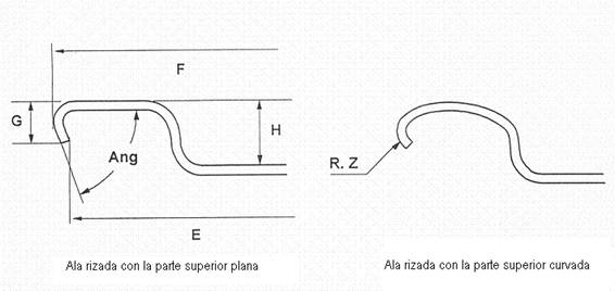
We can define the flange as the outer area of the lid, located between the bowl wall and the outer perimeter. During the closing operation it becomes the cover hook. There are two types of wing: flat and curly.
The flat flange is completely smooth and ends at the sharp edge defined by the cut of the material. That is, its outer edge is the cutting edge. Currently its use is very limited because it is an obsolete technology.
In the curled wing, the outer edge is folded inwards so that the cutting edge is tucked in. This facilitates the closing operation and the stackability of the lids. Within this type there are two versions.
- a) The one with a flat top. See figure nº 2.
- b) The one with the curved one. This second case favours more the formation of the closure, but its manufacturing tooling is more complex, especially if it is a rectangular lid as it is our subject.
Figure 2: Curly-winged versions
In general, for the sake of simplicity, we will consider in our following comments that the wing is of type a).
To determine the width of the flange of a lid, it will be measured externally, if it is of the curly type, the curl will be straightened and in the case of rectangular lids it will be measured in the straight parts.
During the closing operation, when the flange of the lid is tucked to form the lid hook, it happens that in the straight areas this action is a simple bending of the metal that does not present difficulties, but in the corners the material behaves as if we were trying to bend the rods of a fan. The metal located on the periphery of the wing, has to be folded on a radius smaller than the original one, that is to say, it has to be reduced to a volume smaller than the original one. This causes it to flow towards the free part, i.e. towards the cutting edge, or to deform in the form of wrinkles or folds. The second option is very negative, so we have to opt for the first one.
Therefore, in order to facilitate this flow of the material, it is necessary to ensure that its hardness is moderate. The first conclusion is that medium or low hardness tinplate – or TFS – should be used for rectangular caps, the smaller the corner radius, the lower the hardness. T 3 or T 57 hardening gives satisfactory results.
On the other hand, if the width of the flange of the cover is uniform throughout its perimeter, it will happen that when this creep of its material is generated in the corners, it will result in an increase of its width at the time of closing in these areas. This would result in excessive lid hooks on the spokes, leaving the closure unbalanced. To avoid this defect, it is necessary to reduce the dimension of the flange in the four corners, this must be done progressively, starting from the existing dimension in the straight part and reaching the minimum at 45º in the arch. In this way, the smaller initial dimension in the curved areas of the flange will be compensated by its increase in length during the process, resulting in a uniform flap hook all around the perimeter of the closure.
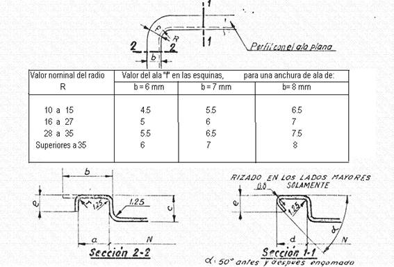
The smaller the radius of the arc at the corners, the greater this decrease in material should be. Figure 3 summarizes the recommended values of this reduction as a function of the nominal width of the wing and the values of the radii.
Figure no. 3: Recommended flange values at corners
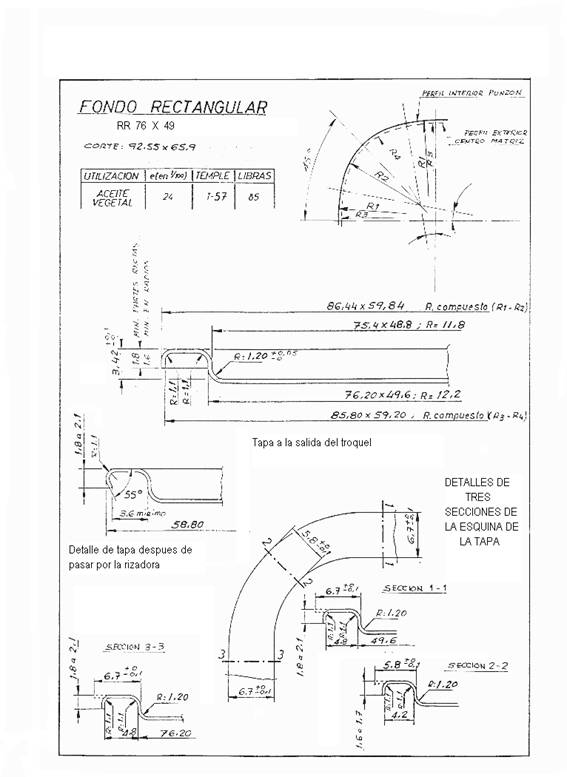
These values are taken at 45º, at its minimum point of length. The cap die design has to incorporate this flange reduction at the radii. On the other hand, the height of the curl should be kept more or less uniform, in order to facilitate the formation of the lid hook at the closure. The latter leads to having to reduce the channel width of the wing in the areas where there is less material, i.e. in the four corners. This causes that the centres of the radii of the outer face of the die centre and the inner face of the punch do not coincide with the centre of the other parts inside the die. In addition, in these two parts, the corners are configured with compound radii. See figure nº 4. In order to determine the values of these radii, it is necessary to define them by geometrical tracing, which is later corroborated in a practical way.
Figure no. 4: Rectangular cover with reduced flange width at corners
. Figure nº 4 shows a RR 76 x 49 format cover with a radius of 12 mm. The above indications have been taken into account in its design. It can be seen that in section 2-2, corresponding to the corner of the cover, the channel width is 4.2 mm, while in the others it is 4.8, i.e. the reduction of material is mostly assumed in this dimension.
After die-cutting, the edge is curled at 55º. This operation can be done:
– 1st: On the two major sides. This is the classic and simple procedure.
– 2nd: Around the perimeter: This requires more complex equipment, but it is the best solution for the closure.
We avoid going into details so as not to deviate from our theme. Suffice it to say that either of the two can give a good closure, although if possible it is better to opt for the second option.
APPLICATION OF COMPOSITE ON THE FLANGE OF A RECTANGULAR LID
Rectangular lids can be gummed using two different techniques:
– By tampon. This is the traditional and still the most widespread procedure.
– Per shower. Provides better quality.
In both cases, if the lid has been curled only on the larger sides, the amount of compound used is less on these two sides, since the access channel for the application is narrower. This causes a lack of uniformity in the volume of rubber applied along the perimeter of the wing.
Another desirable condition is that the compound is applied as close as possible to the outer edge of the flange, as this guarantees its location in the closure in the overlapping area of the cover and body hooks. This is difficult to achieve on the sides with initiated curl, but it is necessary to get as close as possible to this goal.
In the corners, as the channel width of the flange is narrower than on the sides without curl initiated, the volume of rubber deposited will also be reduced. In this area, the compound footprint will decrease from the junction point with the non-crimp sides to the ripple sides initiated.
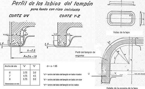
Figure 5 shows the shape of the gummed tampon for a rectangular lid, with the larger sides with a started curl. The dimensions are linked to the flange width of the lid.
Figure no. 5: Dimensioning of a gumming pad
To get a good seal it is very important that the rubber:
– is located in the intended location and does not contaminate other areas of the wing.
– that elastic to fit into the interstices of the closure.
– is well polymerized and bonded to the metal
The amount of compound to be applied to achieve a good seal depends on the flange width of the lid. It is checked by weighing the lid before and after gumming. To calculate the theoretical weight to be applied, the basic data to know beforehand is the volume that once dry it should occupy on the wing. Once this is defined, it is enough to apply the specific weight of the compound used once dry and its percentage in solids – both data to be provided by the manufacturer – to calculate the wet weight of the compound to be deposited on the wing.
The following table defines the appropriate theoretical volume to be deposited on the flange expressed in mm3 per linear meter of flange. Knowing this data and the perimeter of the lid, by a simple proportion is determined the volume per lid and based on it to develop the calculation of the theoretical wetted volume
Flange width of flap Volume in mm3/linear m. ( V )
6 mm 180
6.7 “ 200
7 “ 210
8 “ 250
Formulas: p= V x L x d /1000 P = 100 x p/E
Where:
p = Theoretical weight of dry compound per fund expressed in mgrs.
P = Theoretical weight of liquid compound per fund in mgrs.
d = specific gravity of the compound
E = % solids of the compound
V = Volume of compound per linear metre in mm3/m
L = Development of the perimeter of the cover in mm.
SHAPE AND DIMENSIONING OF THE BODY FLANGE
In general the influence of the bodies is less significant than the caps in obtaining a good seal. Summarily we can say that they must:
– have sufficient rigidity and firmness to properly support the closing operation.
– be sized so that the lid fits smoothly over its mouth.
– the flange of the flange has a suitable radius and width.
We will focus only on the third point because it is perhaps the most important. The first one is linked to the choice of the right metal and the second one is just to take as a reference the dimensions of the centre of the die of the cover die.
The execution of the flange on a rectangular container is usually done in three different ways:
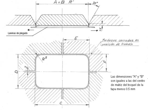
– By folding – or also called “squeezer”. The flange is formed by folding the edge of the body over the outer jaws that embrace it, pushed by the opening expander blades. See figure 6.
Figure no. 6: Squeezer tinning
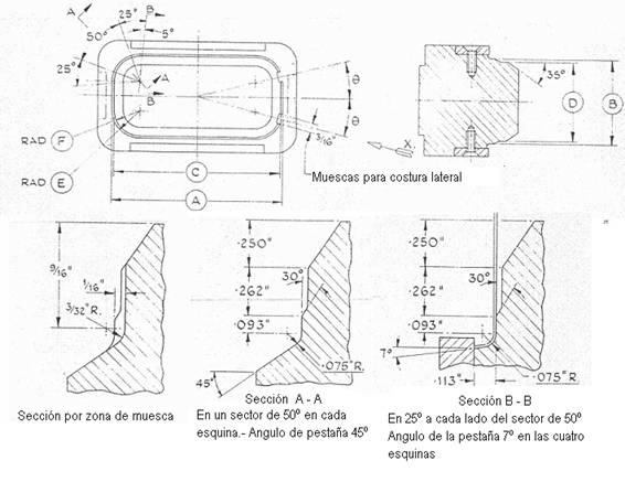
– By tampon. In this case the tab is formed by pressing the body against a tabbing die that has its shape. This type of tooling usually has stops on the straight parts and the angle of the flange varies on the radii. See figure nº 7.
Figure nº 7: Buffer tinning
– By means of a mixed tooling, which combines the technique of folding – expansion – by sheets on the four straight sides of the container and padding on the four corners. This makes the tab not uniform in your profile. In the straight parts of it, the radius is small and the flange tends towards the horizontal, while in the corners the radius is larger and the flange is smaller and with a certain inclination. This is more a problem of appearance than of quality. If the flange is well dimensioned, these variations in shape along the perimeter do not carry over to the closure. Of the three systems this is the best.
The flange value is related to the size of the wing. In the straight areas its value is slightly higher than in the radii. As a general rule this difference is 0.15 mm. This is partly due to the design of the tooling and partly due to the elasticity of the material. This way there is a better correlation between the wing on the spokes and the flange in the same area. The indicative values are given below.
Lid flange width Body flange Body flange on spokes
6 2.55 2.40
6.7 2.85 2.70
7 3.00 2.85
8 3.70 3.50
The flange width will be evaluated externally and results from the average obtained by measuring at different points, as it is difficult to achieve a uniform flange around the entire perimeter.
LOCKING ROLLERS
The most critical part of the sealing tooling is the sealing rollers. The right choice of the profile of the same, especially the first operation, depends on the achievement of a good quality in it. In our case, rectangular containers have special characteristics as we have seen in the different sections. These can be summarized as a lack of uniformity in the flange of the lid and the flange of the body.
For this reason, the roller profiles used in round containers, with a theoretical value of flange and flange equal to the rectangular container that we intend to close (for example flange 7 mm and flange 3), do not usually give a fully satisfactory result. The problem often occurs on the spokes, where “spikes” often appear at the base of the closure and wrinkles appear on the cover hook.
We insist again that when this happens, the best thing to do is not to waste time trying different types of roller profiles until you find one that works, this does not always give results. We must be sure that the flange and flange, especially on the spokes, meet the requirements described above and the caps are of good quality, otherwise we will waste time “fighting” with the seamer. However, if we start with the right components, it is time to study the rollers.
Rulina 1st operation: It is critical for a good closing. Defines the correct hook formation.
Experience has shown that good results are usually obtained by using a profile that meets the following conditions:
– Throat height: The height that would correspond to a round container closure with a flange smaller than that of the rectangular container in question. For example, if the rectangular lid has a flange height of 6.7, a 6 mm flange height roller should be used.
– Throat depth: In this case, the throat depth should be increased by 015 mm which would correspond to a round container closure with a smaller flange. Continuing with the previous example, we would take the throat depth for a 6 mm wing and add 0.15 mm more depth.
In short, it would be a matter of choosing a roller that would be suitable for closing a round container with a flange one step lower than the rectangular one we want to close, deepening its throat by 0.15 mm.
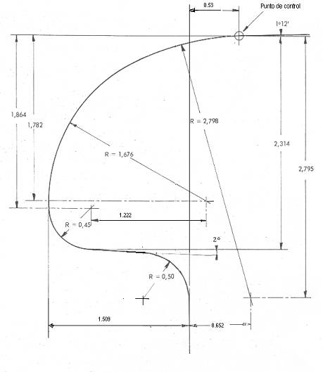
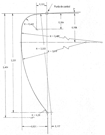
These values have been arrived at in a practical way, but there is a logic to it. Taking into account the reduction of dimensions in the radii of the closure components, the aim is to find a throat profile intermediate to the values that separately would correspond to the straight parts and the radii of the container. Figure 8 shows a profile that works well for rectangular containers with a nominal flange of approximately 7 mm.
Figure nº 8: Roller profile 1st operation
Rulina 2nd operation: Not as important as the previous one. The equivalent of a round container closure of the same parameters can be used, although there are also those with slight adjustments to improve its performance. In figure nº 9 an example is drawn that gives good results; it is also designed for a 7mm wing.
Figure no. 9: Profile of 2nd operation roller
There are other components that must be taken care of such as the mandrel and compression chuck. As well as its adjustments: height gauge, compression spring, etc… But this is already part of what is the technique of the closure, which is not the subject of this work.
CLOSURE MEASURES
The steps to follow to achieve a good closure in a rectangular container are the generic ones for this operation and we have already referred the reader to some works related to them so we will not expand on it.
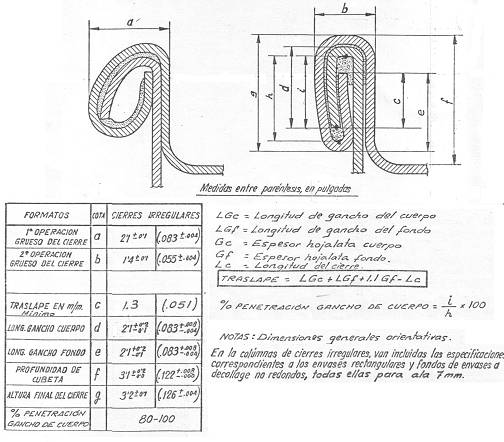
For guidance only, we show the standard values for a closure on a rectangular container with a 3 mm flange and a 7 mm lid flange, which is usually the most general case. Figure 10 shows them.
Figure no. 10: Measurements of a rectangular closure
However, the following remarks should be noted:
– The corner fasteners have slight dimensional differences compared to the straight parts.
– The thickness of the seal is increased by 0.1 mm at the corners.
– If the pressure is increased to try to equalize the thickness around the perimeter, it will create excess closure height at the corners.
– To ensure uniform sealing results, the body should always be positioned on the platen in the same position in relation to the side seam of the platen.
– In seaming machines that use more than one roller for each operation, it is essential that their profiles are identical and their settings are the same.








0 Comments