
Functions of the container body flange. Its dimensioning and the way it is carried out.
INTRODUCTION
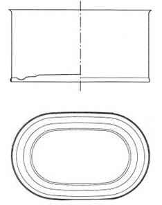
The flange is the flange of the container body at each of its ends, required to perform the closing or joining operation of the container body with the lid/bottom. It is formed by a flat part, almost perpendicular to the wall of said body, and an arch that joins this flat part with the same.
The flanging operation is performed prior to closing and is carried out once the body has been formed. In the case of cylindrical and notched containers, it follows the diameter reduction.
FLANGE DIMENSIONS
The blinking action has two purposes:
1º.- Calibrate the inside diameter at the ends of the cylinder in the case of round containers, or the internal dimensions in the case of a rectangular, oval or other non-cylindrical body. This recalibration is achieved by slightly flaring the ends of the body, and is intended to adjust these areas of the container to the proper fit of the lid/bottom in the closing operation. Therefore, in this operation the tampon dimensions are increased by 0.10 to 0.25 mm in relation to the inside diameter of the body, depending on the size of the container.
This criterion is also applicable in the case of containers with a reduced end -notched-. Drawing No. 1 shows this case, and Table No. I below gives the usual values of the flange zone diameters applied to round containers. The value of this flange diameter is taken at a reference point, located 2.5 mm from the end. The data shown in this table are those commonly accepted in different international standards.
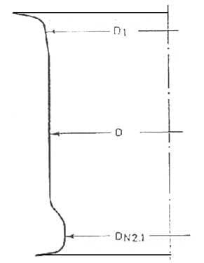
Figure No. 1: Round container body, notched and flanged
| Flange diameter values | ||
| Diameter Nominal |
Diameter Nominal Notched |
Diameter of flanged D1 or Dn2.1 |
| 52 | 52,27 | |
| 49 | 49,40 | |
| 63 | 62,41 | |
| 60 | 59,58 | |
| 65 | 65,28 | |
| 62 | 62,25 | |
| 73 | 72,80 | |
| 70 | 70,13 | |
| 83 | 83,33 | |
| 80 | 80,25 | |
| 99 | 98,99 | |
| 96 | 95,90 | |
| 105 | 105,16 | |
| 102 | 101,73 | |
| 127 | 126,45 | |
| 123 | 123,08 | |
| 153 | 153,35 | |
| 149 | 148,97 | |
| 230 | 229,67 | |
| 225 | 225,09 | |
Table No. I: Values of flange diameter for round cans
Form the eyelash. There are different techniques to form the tab that we will discuss later. The dimensions of the flange are linked to the type of closure we want to make. Therefore they are related to the measures of the flange of the lid/bottom and the size of the container.
The dimension of the flange should also be measured from the reference point, 2.5 mm from the end, as shown in drawing No. 2.
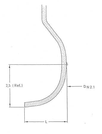
Figure nº 2: Tab
The flange width remains the same for different container diameters as long as the same type of closure is applied. Table II shows these values and their tolerances. European standards have been used to code the type of closure.
| VALUES OF TAB L | ||
| Type of closure | Nominal diameter bottom/top |
Value of the tab L |
| OIII Mini Closure | 52 – 49 63 – 60 65 – 62 73 – 70 |
2,25 +/- 0,20 |
| OII mini closure | 53 – 49 63 – 60 65 – 62 73 – 70 83 – 80 99 – 96 |
2,25 +/- 0,20 |
| Standard OI | 54 – 49 63 – 60 65 – 62 73 – 70 83 – 80 99 – 96 |
2,45 +/- 0,20 |
| Standard locking I | 63 – 60 65 – 62 73 – 70 83 – 80 99 – 96 |
2,45 +/- 0,20 |
| Standard lock II | 65 – 62 73 – 70 83 – 80 99 – 97 105 – 102 127 – 123 |
2,65 +/- 0,25 |
| Standard locking III | 153 – 149 | 3,20 +/- 0,25 |
| Standard IV closure | 230 – 225 | 3,40 +/- 0,40 |
Table II: Flange values according to closure type and container diameter.
EQUIPMENT
The machines that perform this task are called “pestañtas”, although they are also known as “bordonadoras”. As we have already mentioned, they slightly fold the ends of the body, configuring the necessary tabs to later receive the covers and facilitate the closing operation. There are several techniques for making the eyelash, which can be summarized in four.
– Rulina (or reel). It is the oldest type. It makes the flanges by folding the ends by the action of an external roller acting by rotating on a track or roller of larger diameter. The roller has a curvature that matches the outer shape of the flange. The bodies move with their axis in horizontal position. It is only applicable for cylindrical containers and its working speed is low. Today its use is limited to industrial container lines – general lines – of large diameter. See figure nº 3

Figure No. 3: Roll die-cutting machine
– Buffer. They worked by forming the eyelashes by percussing the ends of the bodies by means of a pair of tampons. See figure nº 4
Figure nº 4: Detail of the profile of a tampon flanging tool.
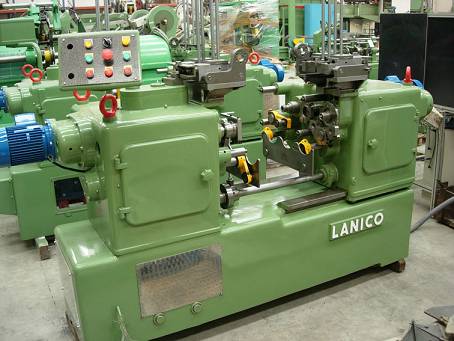
They are fed with the help of a distribution star. There are those that work in horizontal position, older, – see figure nº 5 – or vertical. It has long been the most common technique, although its use is now in decline. It is generally used for cylindrical containers, although it is also possible to use it for oblong or rectangular bodies with large radii at the corners.
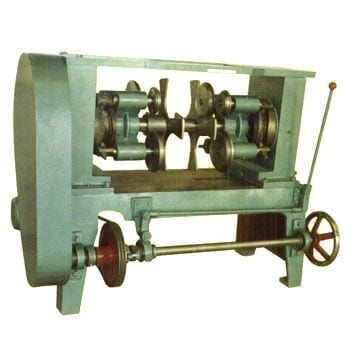
Figure nº5 : Horizontal tampon punching machine
– Spin. This is the most modern form. Its use became widespread with the advent of double reduced tinplate. It allows the flange to be made on very thin and high temper tinplates, without breaking them. The tampons are replaced by heads with a series of small rollers, inscribed in a circumference that coincides with the diameter of the container. The number of them is therefore a function of the size of the container. These rollers or “spin” have a silhouette in the shape of the eyelash. See figure nº 6.
Figure nº 6: Detail of a “spin”.
The “spinners” are mounted on a shaft on bearings, and therefore rotate on themselves when the head is subjected to a rotational movement. These “spin” turns can be motorized or caused by friction against the end of the container body. Due to the way it works, this technique can only be used on round containers and allows high speeds.
– Squeezer. Accepts tabs of any container shape. It acts by expansion. It is the one usually used in rectangular containers, or in containers with a different shape from the round one. This technique can actually be considered a distinct subgroup, which in turn is subdivided into two different ways of working:
– By folding – or also called pure squeezer. The flange is formed by folding the edge of the body over the outer jaws that embrace it, pushed by the opening expander blades. See figure nº 7.
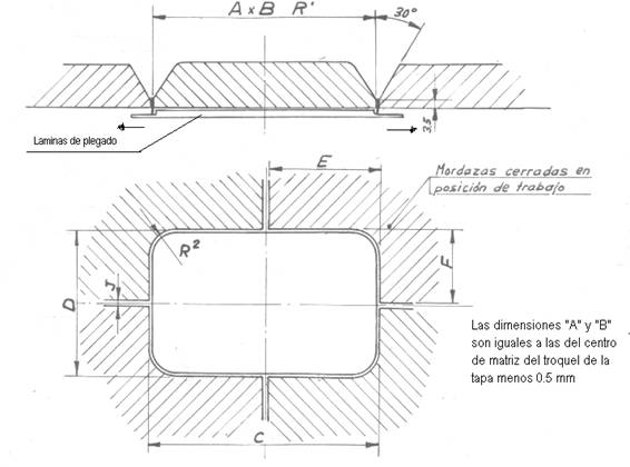
Figure nº 7: Squeezer tinning
– By means of a mixed tooling, which combines the technique of folding – expansion – by sheets on the four straight sides of the container and padding on the four corners. This makes the tab not uniform in your profile. In the straight parts of it, the radius is small and the flange tends towards the horizontal, while in the corners the radius is larger and the flange is smaller and with a certain inclination. This is more a problem of appearance than of quality. If the flange is well dimensioned, these variations in shape along the perimeter do not carry over to the closure. Of the two systems, this is the best.
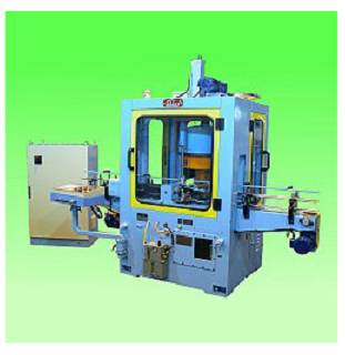
In both cases it is possible to work with the container in horizontal or vertical position. See figure 8 for an example of a horizontal mixed tab. The speeds with these forms of flanging are always lower than those achieved by tampon or “spin”, but it is the best technique to achieve a quality flange on rectangular containers.

Figure No. 8: Mixed pincher – “squeezer tampon” – horizontal
 ASPECTS TO CONSIDER IN THE DESIGN OF CONTAINERS AND LIDS
 RELATIONSHIP OF HEIGHTS IN MANUFACTURE OF AEROSOL CANS
 NECKING BY ROLLER
 PRODUCT TECHNICAL SHEET: CANS “THREE PIECES”
 ENTAILED PACKAGING
 CONTAINERS FOR SAUSED PACKAGING
 PACKAGING TWO PIECES DRD
 OVERHEADS AND PRESSURE PLUGS FOR METAL CONTAINERS
 INFLUENCE OF THE BOTTOM FLANGE OR THE LID ON THE DOUBLE SEAL
 DIMENSIONS FOR CUPPAGES OF ENERALED AEROSOLS


0 Comments