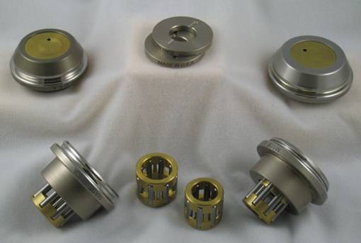
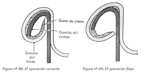
Rulina: It is the part of the seamer that performs the operation of deforming the metal, to configure the hooks of the lid and body and the link between them, resulting in the closure. There are two types, first operation, which forms the hooks and binds them together, and second operation, which crushes them together. Also known by other names such as: trolleys, locking wheels, locking rollers, locking rollers
Rulina 2nd operation: As we have said, it is the one that crushes the hooks of the body and the cover of the clasp. Its function is less important than that of the 1st operation, and its proper definition admits certain margins when it comes to achieving a good closing.
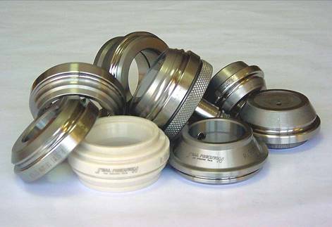
There are many types on the market and their design can vary between them, although it is always linked to the type of closure you want to make and the characteristics of the materials used in the manufacture of the container.
Its critical area of the reel is the throat, which acts on the incipient hooks of the cap and body initiated by the 1st operation reel. This area is called the roller profile and usually has a curved contour, consisting of several arcs of different radii.
This work only intends to give some guidelines on the dimensioning of the profile of the 2nd operation rollers, depending on the type of seal used. Other considerations such as the material to be used in its construction, mechanical characteristics, adjustment of the same in the seaming machine, etc. are treated in other works published on this website.
DESIGN OF THE PROFILE OF A ROLLER 2ND OPERATION
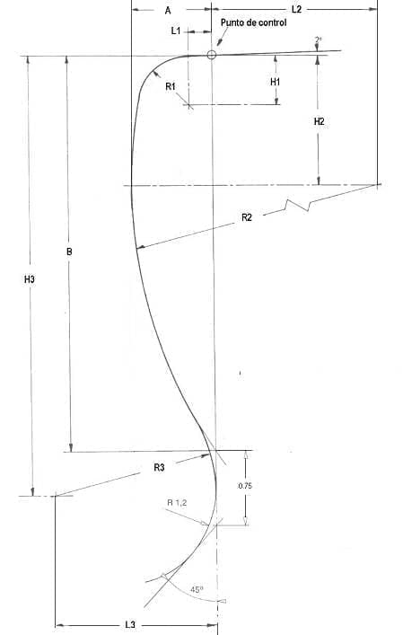
The upper part of this profile begins with a slightly inclined plane, approximately 2º of slope, followed by an arc of small radius that connects with another of greater radius, which ends in a lower heel of double radius. The number of radii can vary from a maximum of 5 to a minimum of 3, although the most common is 3. See figure nº 1.
Figure nº 1: Generic profile of a 2nd operation roller
With this drawing in mind, the following are important points of the profile of a 2nd operation roller:
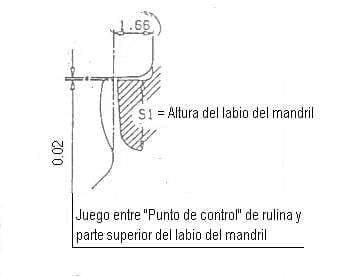
Control point: It is where the upper inclined plane ends and the small radius entry arc begins. The vertical axis that passes through it is taken as a reference to delimit the different heights and depths of the profile, this axis is called the base line, and is usually tangent to the lower heel of the roller. From this point the roller is adjusted in height in relation to the lip of the locking mandrel. The clearance that should exist between this point and the top of the mandrel lip is 0.02mm. See figure nº 2
Figure no. 2: Adjustment of the roller – chuck
Spokes: A three-spoke profile has been reflected in drawing No. 1, which is the most commonly used in this type of parts. Of these, the most decisive is the central one (R2), which has the highest value and defines the outer silhouette of the closure.
Measurements: There are a few averages that can remain constant whatever the profile of the roller, these are the upper angle and the lower radius of the heel. The rest varies as we have already said with the type of closure, which in turn is linked to the dimensions of the flange of the lid and the flange of the body, as well as the characteristics of the materials used in the container. Each company develops the ideal profiles to use in each case, maintaining a certain discretion in their dissemination. This gives rise to a multitude of solutions. We have selected in the following table the measures that experience has shown to be good in each case, although we insist that there are many other alternatives.
| ROLL DIMENSIONS FOR 2ND CLOSING OPERATION | |||||||||||
| TYPE CLOSING |
A | B | R1 | H1 | L1 | R2 | H2 | L2 | R3 | H3 | L3 |
| OIII | 0,55* | 2,53 | 0,33 | 0,34* | 0,17* | 3,32 | 0,88* | 2,77* | 0,8 | 2,91* | 0,8 |
| OII | 0,59 | 2,94 | 0,36 | 0,37 | 0,18 | 3,62 | 0,96 | 3,03 | 1,37 | 3,31 | 1,37 |
| OI | 0,64 | 3,17 | 0,39 | 0,4 | 0,19 | 3,9 | 1,04 | 3,26 | 1,27 | 3,52 | 1,27 |
| I | 0,66* | 3,1 | 0,4 | 0,41* | 0,2* | 4,06 | 1,11* | 3,4* | 0,8 | 3,48* | 0,8 |
| II | 0,69 | 3,42 | 0,42 | 0,43 | 0,21 | 4,2 | 1,12 | 3,52 | 1,37 | 3,8 | 1,37 |
| III | 0,73* | 3,44 | 0,45 | 0,46* | 0,22* | 4,5 | 1,20* | 3,77* | 0,8 | 3,82* | 0,8 |
| Approximate measurements | |||||||||||
The following comments should be made on this table:
– All measurements are rounded to the hundredth of a millimetre. Therefore, slight errors may occur in an exact geometrical drawing.
– The dimensions marked with an asterisk (*) are approximate.
– No tolerances are given. These should be as few as possible.
The practical results of rollers with these profiles depend not only on their geometrical configuration, but also on the quality of the materials used in their construction, the surface finish, machine adjustment, design of the closing head, etc.






0 Comments