SUMMARY
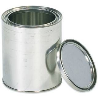
Description of the necessary operations, as well as its tooling, for the manufacture of a double-friction plug – or double closure – used in containers to contain paints or similar.
PREAMBLE
It is usual to pack paints and other products consumed in the home in boats, with closures that allow their use in several times. Typical example are the containers with friction closure of which there are diversity of types in the market.
We have already discussed this issue in other works published on this Web. Specifically on the various types of friction closures the article can be read:
– Container closures to contain paints
Now we will focus on the way and manner of manufacturing a plug of the characteristics used in these closures. In particular, a double-wall closure plug, called double friction (DF). The details that are given here, continue and complement the work:
– Tools for hoops – Paint containers
in which it developed, in the same terms that we will do here for the stopper, the operations and stamping necessary for the manufacture of rings for these types of closures. In other words, both jobs can be integrated into one.
TOOLS
For the manufacture of the plug type double friction is required to break it into two phases or operations, whose purpose is as follows:
– First operation: Cut and embed an outline of the cap
– Second operation: Complete the conformation of it and determine the final measures
As in the case of hoops, these two operations could be done in a transfer press or also in a double-effect press, but the simplest and most economical way is to make them on two simple swan neck presses. The first equipped with a warehouse of material bands, and the second one with a unit feeder.
FIRST OPERATION
The plug has to fit perfectly to the ring, therefore it has a “U” shape that adapts to the inside of it. Therefore, in this area, the dimensions of both are interrelated. In the aforementioned work:
– Container closures to contain paints
the relationships are indicated in terms of the corresponding dimensions.
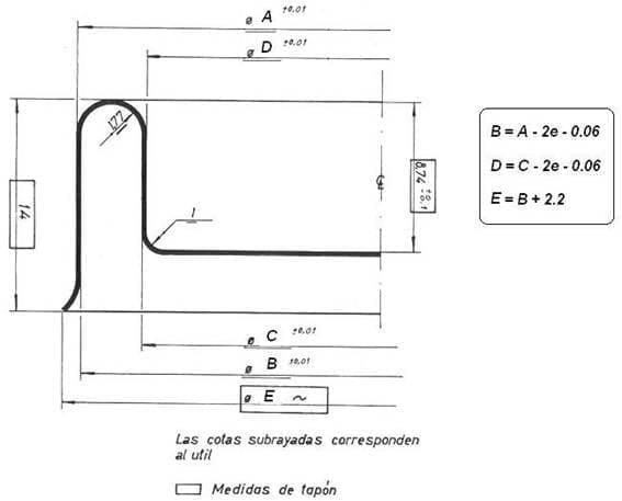
Figure 1 shows a section of the profile of the first operation of the cap, which we have taken as an example. In it appear two types of dimensions, some in the form of a letter, which correspond to the diameters that change depending on the size of the container, and others valued in millimeters, referred to the heights of the piece. The latter are appropriate for packaging formats with a capacity between ½ and 1 liter. For diameters of larger or smaller boats, these heights will vary proportionally, as in the case of hoops.
Figure No. 1: Section of the 1st operation of a DF plug
In the drawing the different dimensions, some are highlighted within a rectangle, they refer to the finished piece, others are only underlined and with tolerances, these are measures of the tool and their relationship to each other is reflected in the table of formulas that it accompanies drawing no. 1. The means indicated in height, which are part, must be taken as advisable values for a container diameter of around 100 mm.
The diameter of cut, necessary for the formation of the stopper, is approximately between 28 to 32 mm greater than the diameter A of the drawing, varying with the format of the container, all for capacities between ½ and 1 liter. The width of the “U” of the double closure is defined by the dimension of the ring as already said, and is usually about 6 mm. The radius of curvature of the metal in the “U” is defined by the values of the friction diameters, see figure no. 1
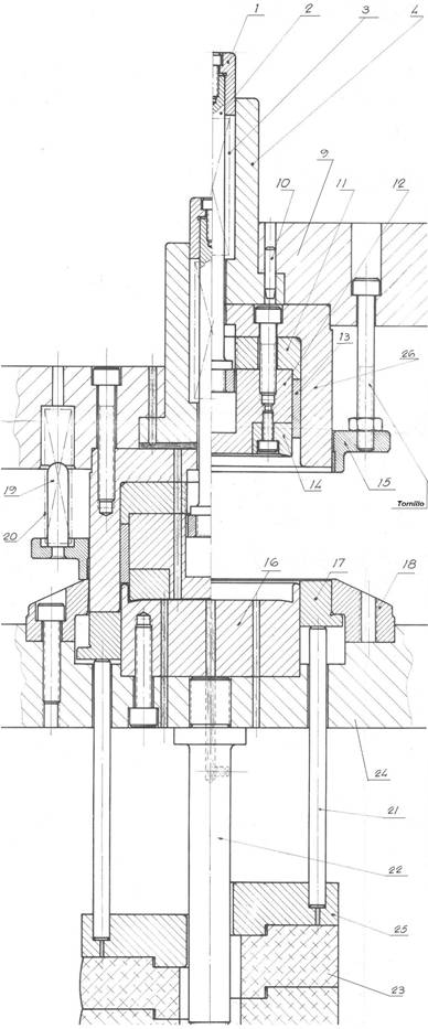
Figure 2 presents an example of a die for this stopper. We will briefly comment on its characteristics since it is a very conventional tool.
This die performs the following sequential actions:
– Cut a metal disk from the strip fed to the press from the strip magazine
– Inlay the friction walls of the plug
Figure nº 2: Die for the first operation of DF plugs
Because it is a die that performs a cutting operation, it is advisable to be guided, this will ensure the quality of the cut and the life of the punch, blade and other pieces that form it. It is quite similar to a tool used for making funds, in which the center generates a deep drawing, and the external wall – wing curl – is much larger. To facilitate the execution of the second operation, the outer cutting edge should be slightly curved, see figure No. 1, thus the external curl will start well in said operation.
The dimensions of the walls of the “U” will have the same value in both the first and the second operation. To see the law of formation of the diameters that form these walls, we return to the work:
– Container closures to contain paints
As already mentioned for the case of the ring, in the dimensioning of the parts of the tool, it must be borne in mind that there is always a slight deformation due to elasticity of the plug, in relation to the measurements of the tool. This occurs mainly in the diameters of the friction walls. Since the fit between the ring and the stopper must be very precise to maintain an effective tightness, this recovery of the material must be taken into account, so that the dimensions of the die will not coincide with those that are desired to be obtained on the piece.
SECOND OPERATION
The sketches obtained in the first operation fall to a discharge, which deposits them on a magnetic lift, which in turn places them in a fall by gravity, which brings them closer to the second operation press. It must be equipped with an automatic system for feeding parts, mechanically or pneumatically driven, synchronized with the stroke of the die.
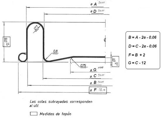
The second operation ends the plug, transforming the initial sketch. In figure 3 the resulting piece of this second operation is presented. The tasks of this operation are the following:
– Recalibrate the walls of the “U”, to ratify its appropriate measures.
– Turn the outer edge of the cap, forming a toroidal curl, which will facilitate the handling of it, especially at the time of opening the container, since on it you can leverage, to remove the plug from its housing in the ring.
Figure No. 3: Section of the 2nd operation of a DF plug
On the drawing No. 3 the different diameters have been bounded using the same letters as in drawing No. 1, except for the one corresponding to the outer diameter and the central panel which are different.
To the right of the drawing, the formulas for the determination of each diameter appear, which partially coincide with those of the first operation. The heights appropriate to this example are also indicated, which are related to those applied to the first operation.
Defined in this way the profile of the plug, we will proceed to design your corresponding tool. The same has to perform the tasks indicated above. Figure 4 shows a vertical section thereof.
It is a forming die, without any cutting function. This simplifies its construction somewhat. The first operation piece that is pushed on the bottom of the tool by means of the feeder, is positioned correctly on it with the help of a pair of stops, which stop the inertia of movement of the sketch. See pieces no. 17 to 21 of the drawing. These two stops are located on the opposite side of the arrival of the piece and separated 90 °. When the upper part of the tool lowers, they are retracted by the action of an inclined plane positioned on the external face of the piece No. 6 of the upper part of said tool. At the end of the cycle, they return to their initial position by the action of spring number 11.
Figure nº 2: Die for the second operation of DF plugs
The piece no. 16, which forms the outer curl, can be manufactured with a channel on both sides, thus turning it over when said channel is worn with the work, and in this way doubling the life thereof. Piece nº 5 is a shim that allows, acting on its height, to adjust with precision the action of nº 7 that is a presser-ejector of the tampon
The operation of the die is relatively simple and can be followed with the study of drawing no. 4.
METAL
Repeating the aforementioned for the case of rings, the tinplate or TFS used in the manufacture of plugs should be of low temper and a thick gauge, in order to eliminate risks of cracks, breaks and exaggerated deformations due to internal stresses of this material. For bottle caps that will contain ½ to 1 liter of product, appropriate values would be: Temple T2, caliber from 0.24 to 0.27 mm, that is to say two or three hundredths less than the material used for rings, since in this case the efforts demanded of the metal are slightly lower. Its coating will depend on the aggressiveness of the product to be contained.






0 Comments