Back to
– By clicking here you can access the 1st part of this work.
5º.- EVALUATION OF THE CLOSING
Closure assessment is the methodology used to judge its acceptability. It is therefore related to the specifications and requirements indicated by the manufacturer. These vary for each format and type of packaging. Therefore, in order to evaluate a fastener, it is first necessary to have the complete table of specifications that the fastener must comply with.
It often happens that an apparently normal and within specifications in its external measurements, presents upon further analysis, a series of defects that make it incorrect.
By means of the appropriate evaluation or examination, it is possible to guarantee or not the tightness of the same. The review of a closure comprises four phases, each of which provides a wealth of qualitative and quantitative information. These are:
1st Phase: Visual Examination and External Measurements.
2nd Phase: Dismantling and/or sectioning of the closure
3rd Phase: Direct and Indirect Internal Measurements and Internal Defects
4th Phase: Leak detection.
PREPARATION
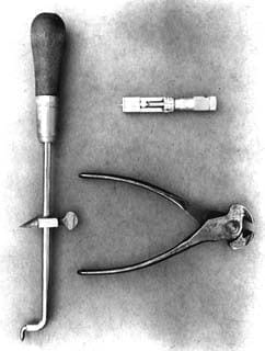
A number of basic tools are required to open a fastener:
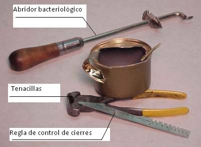
1º.- Bacteriological opener: Consisting of a rod with a handle, which ends in an angled tip. A pointed blade slides along the rod to cut the metal. See figure nº 16. If it is not available, metal cutting scissors with curved tips can be used.
Figure 16: Basic material for opening a fastener
2º.- Pincers. See figure nº 16. They are small and handy pliers with a wide mouth, which allow you to manoeuvre efficiently.
3º.- Closing control ruler. This is the simplest measuring element. See figure nº 16. It does not allow exact readings, but it has the following minimum elements:
Ruler graduated in mm. with the “zero” at the end to be able to measure, by direct support of the tip, different parameters such as: diameter of the container, length of the closure, etc.
– Set of calibrated notches for reading the thickness of the seal.
– 2″ (50.8 mm) housing to evaluate the number of funds that will fit in this size.
– Calibrated heel for checking the depth of the cuvette.
4º.- Hook Gauge. It is a micrometer of special design for the measurement of the parts of the fastener.
5º.- Gauge with dial to measure the depth of the cuvette.
6º.- Gauge with dial to measure the thickness of the seal.
7º.- Special saw for cutting the fastener
8º.- Thickness micrometer for metal thickness.
9º.- Closures projector
In addition, the seamer needs to be adjusted:
10º.- Set of feeler gauges (blades) for roller heights
11º.- Set of rod gauges for the distance of rollers
12º.- Inside micrometer for baseplate height
13º.- Dynamometer for base plate pressure.
Each of these elements will be described below. Any evaluation of a closure will require the use of this instrumentation, which must also be calibrated so that the zero is correctly set.
Two methods of analysis are generally used. The first is to open the lock completely. This requires disassembling the double seam, measuring the components, and recording their dimensions and observations from your examination. The second method is the sectioning of the closure. To perform this type of analysis, the closure is cut perpendicularly, and the resulting cross-sectional area of the closure is projected onto a screen, or placed under a microscope, to allow accurate measurement of the body hook, bottom hook, effective overlap, and with the aid of a scale, the penetration of the body hook.
The seaming method can be performed quickly on cylindrical cans. However, the vulnerability of irregular can corners makes it necessary to section each corner to determine the overall quality of these areas. This is a lengthy task and is often considered to be more time consuming than the full opening method.
One of the main disadvantages of the evaluation of the quality of the closure by the sectioning and projection method is that it does not reveal the ratio or degree of compactness or the level of wrinkling of the lid hook.
EXECUTION
To check the quality of a closure, the normal way to go is to break down each of the phases listed above into a series of steps, which are as follows:
1st Phase: Visual inspection and external measurements
A.- Visual inspection
1.- Visually inspect it for the possible presence of: Skidding, cutting edge, false closure, “peak” in assembly, peaks in the closure, flattened flange, flattened curl, sunken bottom, roller skip, scratched closure, broken mandrel, compound ejection, lamination at the base of the closure, irregularities in the closure, etc.
B.-External measures:
2.- Cell Depth
3.- Length of the fastener
4.- Fall in the union
5.- Thickness of the seal. Compactness
2nd Phase: Disassembly of the closure
6.- Cut and remove the centre of the bottom of the container.
7.- Closing sectioning
8.- Separate the closure, if the “scrapping” procedure has been chosen, or
disassembly (1st procedure).
9.- Preparation of the closing for its projection. (2nd procedure)
3rd Phase: Internal measurements
10.- Carry out the following measures:
– body metal thickness or gauge
– bottom metal thickness or gauge
11.- Tightening of the lock. Determine clearance – (critical parameter)
12.- Measure:
– body hook length
– bottom hook length
– body hook penetration (critical parameter)
– overlap (critical parameter)
13.- Check internal defects of the seal
4th Phase: Leaks
14.- Leak detection.
Let’s look at each of these steps:
1ST PHASE: VISUAL INSPECTION AND EXTERNAL STOCKINGS OF THE SEAL
A.- VISUAL INSPECTION
The first thing to do with a fastener for analysis is to visually inspect the outside of the fastener. Many defects can be detected with the naked eye, or by direct touch, without the use of any measuring instruments and materials. The list of faults of this type are identified as “external seal defects”.
Some defects can be seen much more quickly by tactile recognition than by visual inspection. Visual inspection is carried out by running your finger over the inside and outside of the fastener to check for roughness, sharp edges, ripples, etc.
The main external defects that can be located by this system are:
Skating
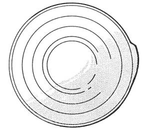
Incomplete formation and crushing of the closure, caused by an incomplete 2nd operation, caused by a displacement of the container between the compression plate and the closure mandrel. It is characterized by the fact that part of the closure has the profile of the 1st operation. See figure nº 17. Generates leaks. This defect is detected by a greater thickness of the closure and a slight deformation of the bottom of the container.
Figure no. 17: Slippage defect in a fastener
This defect can be caused by:
– Insufficient pressure on the compression plate.
– The locking rollers do not rotate freely.
– Worn locking mandrel
– Oil or grease on the mandrel or on the compression plate
– Inadequate positioning of the bottom on the mandrel due to dimensions or shape, or too tight or too loose.
– Poor timing of closing operations
Cutting edge
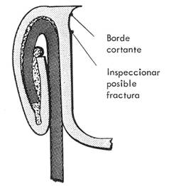
Presence of a sharp edge on the inside of the summit of the clasp. See figure nº 18. This very sharp edge is caused by the bottom material being forced over the top of the mandrel lip during closing. It usually occurs in the weld area of the body, but can also occur anywhere on the fastener.
It can be recognized by running your finger around the inner periphery of the clasp. This is a dangerous defect, as it can cause a fracture of the metal below the cutting edge. If this happens there is a certain danger of leakage.
Figure no. 18: Shear edge defect
It can be caused by:
– Wear on the locking mandrel.
– Roller profiles too narrow
– Too much tightening of the second operation rollers.
– Excessive base plate pressure.
– Mandrel too low in relation to the rollers.
– Excessive sealing compound
This defect may present itself in a more attenuated form, without showing a sharp edge, but simply a sharp edge. In this case the defect is minor and happens for the same reasons but in less intensity, it is designated as live or straight edge.
False locking
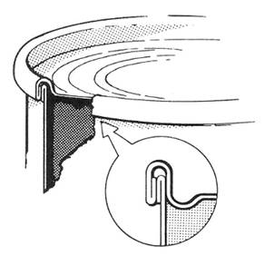
Failure in the crimp between the body hook and the bottom hook. See figure nº 19. It is similar to the defect caused by a flattened flange, where part of the flange is bent against the body of the container, without wrapping around the bottom hook, but without protruding through the bottom of the closure. Assumes the presence of leaks.
Figure nº 19: False closure
It can be caused by:
– Damaged, bruised or crushed body tab.
– Body tab “chubby”. That is to say, curved downwards, caused by a bad adjustment of the flange, or by a bad condition of the flanging tool.
– Damage to the curl of the wing at the back: bumps, marks…
– Incorrect positioning of the bottom on the locking mandrel.
– Product or foreign matter deposited on the flange.
False fasteners are a defect sometimes difficult to see, because they are covered by the bottom hook, they are always very dangerous. It is necessary to detect them by observing the closure at the bottom.
“Pico” in the assembly
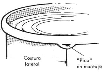
Presence of a ridge at the base of the zip, in the area of the side seam of the body. It consists of a projection of the bottom hook below the clasp. See figure nº 20. It leads to the absence or reduction of the bottom hook in that area, and therefore the possibility of leakage. If it extends more than 1/3 of the length of the fastener below the fastener or by more than 10 mm along the length of the fastener, it is a major defect.
It can be caused by:
– Excessive body hook
– Excessive amount of rubber
– Second operation performed with too much pressure
– Product or foreign matter inside the closure.
It is also called “falling into the joint”.
Closing peaks
The peaks can occur not only in the area of the side seam, but at several points in the same zipper, if these points are very pronounced are called “V-peaks”.
Sometimes this peak can degenerate into a fracture at the base of the clasp, which is very difficult to observe. The use of a magnifying glass is required for viewing. Closures with less than the specified thickness are at risk of this defect.
The main cause of this defect is the excess pressure of the 2nd operation roller and/or the base plate.
Flattened tab
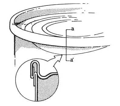
This defect has the flange bent against the body, without being rolled up with the bottom hook and appears clearly below the base of the clasp. See figure nº 21. When it manifests in a severe form, it affects the adjacent and lower part of the body. It generates a defective joint. It is similar to the false zipper but more visible.
Figure nº 21: Flattened tab
The most frequent causes of this defect are:
– Damaged tab during handling, transport, filling or in the seamer feeder.
– Very chubby eyelash.
– Deformed flange due to product or foreign matter deposits.
– Misalignment of the container in the closing position.
A similar problem can occur when it is the bottom curl that has been damaged, resulting in the defect “crushed curl”. In this case part of the bottom hook is completely unhooked from the body hook, and also hinged down against the body, exposing the edge of the bottom.
Sunken bottom
Great deformation of the bottom in the area of the bowl, giving rise to the separation of the hooks from each other, and can get to be part of the curl of the bottom turned, so that the flange is exposed.
Their main reasons:
– Mandrel too low in relation to the base plate, or better still compression plate too high.
– Excessive pressure on the compression plate
– Clippings caught in the seamer head.
Roller skip
Area of the fastener that is not tight enough, caused by a jump of the locking rollers. It always occurs in an area next to the side seam, especially when the seam is crimped, which is when it is thicker, and causes the rollers to “trip” over it, and rise slightly at the seam exit.
It is observed by disassembling the closure and examining the bottom hook for wrinkles on both sides of the seam. Their location will depend on the direction of rotation of the rollers.
Its causes are:
– Excessive closing speed.
– Seam too thick.
– Breakage of the idler arm adjustment spring.
– 2nd operation roller bearing too weak or too slow.
Striped zipper
It is a friction or abrasion of the bottom bowl wall, which appears after closing, and is caused by a sliding of the bottom with respect to the mandrel.
It can cause a detachment of the protective varnish, with the likelihood of subsequent corrosion of the metal if the tin is affected.
Possible causes may be:
– Insufficient compression plate pressure.
– Damaged locking mandrel.
– Excessive vertical clearance of the spindle shaft
– Oil or grease on the mandrel
Precisely to avoid this defect, it is not recommended to use mandrels with knurled lip.
Broken mandrel
Defect that manifests itself because a part of the seal is not properly tightened, presenting an irregularity on the inside, i.e. on the wall of the flask. It is caused by a gap or nick in the lip of the mandrel.
It is caused by the chuck lip being chipped or “nicked” as a result of jamming or other reasons.
Compound expulsion
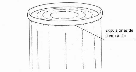
Small particles of compound emerging from the base of the closure. Its origin is in the expulsion of the same outside the closure, between the bottom hook and the body. It can occur in part or all of the closure. See figure nº 22
Figure nº 22: Compound expulsions
Probable causes:
– Excess sealing compound
– Wet or insufficiently dried sealing compound.
– 2nd operation pulleys too tight.
Laminations on the base of the closure
Mark or stripe in the vicinity of the base of the closure, parallel to the summit of the closure, indicating the presence of a lamination in this area. It can damage the protection of the varnish.
The most likely cause is the use of a 2nd operation roller that is too tight or too narrow in profile. It can also be caused by a worn or large 1st operation roller.
Closing irregularities
Although it is very rare, sometimes there may be irregular-looking closures, with a lack of uniformity in thickness and length, slight laminations in some areas of the closure or occasional peaks.
The main cause of these defects can be a tilted mandrel or compression plate, either due to faulty assembly or deformation of the mandrel or compression plate. If the mandrel diameter is small, it also causes irregularities in the seal.
B.- EXTERNAL MEASUREMENTS:
They will take place at various points on the periphery of the closure. Only the measurements of three points located at the vertices of a hypothetical equilateral triangle inscribed in the bottom will be recorded. The closest point of the side seam must be at least 10 mm from the side seam.
For non-cylindrical containers, measurements shall be taken at three points, one at the point opposite the side seam and the other two at the ends of the straight part of the closure on the long side. In non-cylindrical containers, the most problematic points for the closure measurements are the radii. An oval container is considered to have the largest curved sides being the straight sides. The values must not be averaged.
MEASUREMENT OF THE CUVETTE DEPTH
The trough depth is measured from the top of the seal – top of the seal – to the base of the bottom trough wall radius. The original trough depth of the bottom is modified by the height of the lip of the locking mandrel.
This depth varies according to the type of container, but should never be less than the height of the closure. Its normal value after sealing should be 0.10 to 0.30 mm. deeper than the length of the seal, so that the mandrel allows the bottom and the body a good coupling with the compression plate during the execution of the seal. In the case of the “mini-closing” this difference increases as we will see later.
In the conventional closures of containers the depth of the tray varies between 3 to 3.50 mm. although there are several exceptions, such as carbonated beverage containers, in which it has a greater value due to the convex configuration of the lid and the presence of the ring, and the same happens in general with easy-open lids.
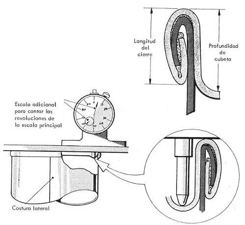
The trough depth should be checked by means of a suitable gauge of the type shown in Figure 23. To measure this depth, the gauge bar is placed over the top of the seal. The tip of the gauge is placed at the lowest point adjacent to the cuvette wall, but at least 10 mm away from the junction. It is also important to avoid the horizontal bar resting on the joint or the tip touching any code stamped on the bottom. In the shape packs it is measured at four points, each one located in the area of each radius.
Figure no. 23: Measuring the cuvette depth
Variations in the depth of the tray can indicate the poor condition or adjustment of the tooling or the machine.
An increase in the trough depth, uniformly and to a much lesser extent than in the case of a “die bottom”, i.e. without losing the double seal, is a defect caused by the mandrel fitting on the bottom being too hard, preventing the normal flow of material in the seal. It can also be caused by a lack of pressure on the base plate. Generates unbalanced hooks (short bottom hook).
If the increase in trough depth is not uniform, the causes may be the same or rather the lack of fullness of the mandrel – warped mandrel -. The effects are the same.
MEASUREMENT OF THE CLOSING LENGTH
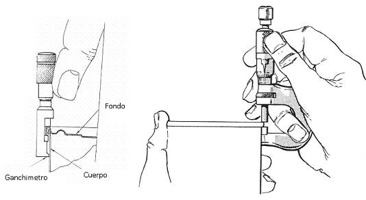
It is a question of evaluating the height of the closure. To do this, a hook or micrometer is used, as shown in figure 24, i.e. keeping the flat surface of the micrometer against the body of the container.
Figure no. 24: Measuring the length of the fastener with hook or micrometer
The actual length of the fastener is also a good reference for the quality of the fastener in relation to the theoretical length of the corresponding type of fastener. This measure is related to the degree of tightness of the fastener, the longer the fastener, the greater the degree of tightness of the same, therefore it can be said that the length of the fastener depends on how the second operation roller of the seamer works.
A 1st operation roll with a profile that is too wide or worn, loose or low in relation to the mandrel, will result in a long closing length. If your profile is narrow, too tight or too high it will result in a small closure length.
A 2nd operation roller with a large or worn profile, loose or low in relation to the mandrel, will influence the length of the fastener even more, giving a large result. The opposite will give a small result.
The normal range of this measurement is from 2.6 to 3.2 mm, depending on formats and types of fasteners used, although there are also exceptions when it is a mini fastener. In general, no difference in this length should be greater than 0.15 mm in the same package.
MEASUREMENT OF THE FALL IN THE UNION
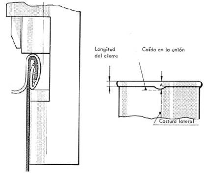
The drop in the seam is the increase in length of the zipper at the point where it intersects the side seam. It is logical that at this point the height of the fastener increases because the body hook is thicker due to the overlapping of two metal thicknesses, which is necessary for welding. This can result in a decrease in the length of the bottom hook.
To measure this drop in the joint an ordinary micrometer or better a hook gauge should be used, as shown in Figure No. 25. To be measured at the point of maximum drop.
The drop at the joint must never be greater than 20% of the average length of the fastener. It is expressed by:
Sag at joint = Length of closure at joint – Average length of closure
Figure no. 25: Measurement of the sag at the junction
Sag at the joint = A – average length of the fastener.
In the area of the fall, the closure is also thicker for the same reason mentioned above.
SEAL THICKNESS MEASUREMENT
This is another secondary indicator of the degree of tightness of the fastener. It is a function of the metal thickness of the bottom and body and the pressure of the second operation roller. It also depends on the weight of compound applied. It should not vary more than 0.10 mm around the fastener, although this reference is unreliable as there are many exceptions.
This measurement, like the previous ones, is made in three positions in the form of an equilateral triangle. To make this measurement, a special gauge or a hook gauge can be used. The use of the gauge gives us a much higher accuracy than the micrometer and is less susceptible to measurement errors by the operator. See figure nº 26.
Figure no. 26: Measuring the seal thickness by means of gauges
When using the hook gauge, the index finger should be swung slightly with the index once it has been placed on the fastener, until the angle it forms with the horizontal is the same as the angle the wall of the cuvette forms with the vertical, as shown in figure 27, taking special care not to press excessively on the fastener, as this may give rise to a false measurement.
Figure no. 27: Measuring the seal thickness by means of hook gauge
There is another very simple way to measure approximately the thickness of the fastener, it consists of using a “fastener control ruler” (see figure nº 16), it has a series of notches calibrated with different measures. The one that best fits the thickness of the fastener will give us a fairly approximate assessment of its value in mm.
2ND PHASE: DISASSEMBLY OF THE CLOSURE
In order to determine a number of key factors for the integrity of the seal, such as degree of tightness, body and bottom hooks etc, it is necessary to disassemble the seal. There are two ways to prepare the closure for study:
1.- Total disassembly or “scrapping” of the same, for direct measurement.
2.- Sectioning for evaluation by projector,
The starting point is a series of operations common to both paths, although each one requires a final preparation.
The steps to be taken are as follows:
Common Operations
:
1º.- Cutting and extraction of the central panel of the bottom.
2º.- Cutting of two opposite sections of the fastener.
Differentiated operations:
3º.- For study by disassembly
a.- Removal by tearing the rest of the panel.
b.- Disassembly of the bottom hook
c.- Study of the disassembled closure elements
4º.- For study by projector
a.- Fold back the sections produced and separate them from the packaging.
b.- Uniform the edges of the sections with fine sandpaper.
c.- Place the sections on the projector for evaluation.
d.- Detach the cut sections of the hook from the bottom, for the independent study of both hooks.
Let’s go into detail on each of the steps outlined below.
1º.- CUT OF THE CENTRAL PANEL OF THE BOTTOM
It is the operation prior to the scrapping or sectioning of the closure. It is a necessary task to be able to access it easily. This requires the use of a bacteriological opener or, failing that, a pair of scissors with a curved tip to cut the sheet metal.
Figure 28 illustrates the operation of the bacteriological opener. It is necessary to stick it in the centre of the bottom and adjust the opener so that it cuts a disc with a radius of 6 to 12 mm from the wall of the trough to the cutting edge.
Figure 28: Cutting of the central panel of a backdrop
Once the central disc has been cut, it is removed. It is advisable to use safety gloves for this operation to prevent the risk of injury from sharp metal edges.
2º.- CUTTING OF A SECTION OF THE CLOSURE
This operation is imperative only if the closure is to be inspected by means of its projection, but it is advisable to do it in either case. To section the cut, starting from the container with its central panel removed, you can use a special thin-cutting saw, making two cuts in the closure. To obtain a clean cut, without burrs or deformations, it is necessary to use specific saws for this purpose existing on the market, which have two circular blades of about 100 mm in diameter, with a thickness of 0.35 mm, with a pitch of 24 teeth / inch and a rotational speed of 520 rpm. See figure nº 29
Figure no. 29: Saw for cutting fasteners
The cuts should be made in line with the diameter of the container and parallel to its axis, and should be at 90º to the right of the side seam. Then cut another section on the opposite side of the container. See figure nº 30
Figure no. 30: Cutting of a section of the closure
3º.- PREPARATION OF THE CLOSURE BY DISASSEMBLY
Its purpose is to detach the bottom hook from the container, so that it can be analysed separately.
Photo nº 31: Sectioned container
Starting from the sectioned container (Photo no. 31), tear with the help of the
using pliers or special pliers for this purpose, the rest of the bottom that has been left after cutting the central panel, between the cut and the top of the fastener (Figure nº 32).
This takes a bit of practice, although it is an easy task. By means of the pliers, it is pulled in the opposite direction to the radius of the panel and around the entire length of the fastener. A metal strip that includes the rest of the panel and the wall of the trough will be torn. This way we will have the bottom hook independent from the rest of the container.
Figure no. 32: Preparing to remove the bottom hook
To remove the hook from the bottom, gently and carefully tap down the cutting edge of the hook with the flat side of the pliers. See extraction sequence in photos 33. In this way we will be able to gradually detach the hook from the bottom of the clasp.
Figure no. 33: How to remove the body hook
In this way, we will detach the body hook from the fastener with great caution, leaving the assembly as shown in drawing nº 34. We have now completed the preparation of the can for the examination of its closure.
Figure 34: Container prepared for examination of the closure by scrapping
4º.-PREPARATION OF THE CLOSURE FOR PROJECTION
Starting from a previously prepared container as shown in Figure 230, i.e. once two sections of the closure have been cut, fold back the section produced, as shown in Figure 35, and separate it from the rest of the container by sectioning it with a pair of pliers, taking care not to affect the closure.
Figure 35: Separation of the cut section of a fastener
The surface of the cut section will look rough and burrs due to the action of the saw, it is necessary to smooth and uniform the section with the help of a fine sandpaper. Now we can take this fragment to the projector and display it for evaluation.
With great care, the hook can be detached from the bottom of the closing piece, so that the impression produced by the rollers when acting on the mandrel, roller jumping, falling in the joint and other defects can be checked.
3RD PHASE: INTERNAL MEASUREMENTS
With the closure ready, we enter the phase of measuring its parameters.
5º.- MEASUREMENT OF THE THICKNESS OF THE METAL OF THE BODY AND BOTTOM
The actual metal thicknesses of the body and bottom must be known, as they are necessary data for further calculations. A gauge of the type shown in Figure 36 shall be used for this measurement.
Figure no. 36: Micrometer for metal thickness measurement
A micrometer with a digital or dial readout can also be used. Whatever instrument is used, it should be checked at regular intervals to ensure its accuracy.
To make these measurements on a sample container, some triangles must be cut in the shape shown in figure nº 37, on which we will determine the thickness of the metal.
Figure no. 37: Thickness measurement points on a container
The point P, at which the measurement is to be taken, must be at least 10 mm from the edge of the container.
If the triangular samples are varnished and/or lithographed, these coatings must be removed by applying a solvent-impregnated cotton swab if an error-free reading is required.
6.- TIGHTENING OF THE FASTENER. DETERMINATION OF FREE SPACE
This is a critical parameter and we refer to what we will discuss in detail in the section “ACCEPTABILITY OF CLOSURE”.
7.- HOOK MEASUREMENT
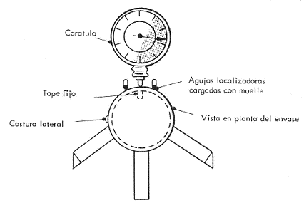
Bottom and body hooks should be measured at two opposite points on two-piece packs, and at the 10 o’clock and 14 o’clock position, 12 o’clock being the side seam, on three-piece packs. The lengths of the body and bottom hooks can be measured by means of a hook meter if the fastener has been disassembled, but if we wish to obtain a much more precise measurement, a fastener projector should be used if the fastener has been previously sectioned.
If we use the measurement by hookmeter with disassembly in the clasp, we can take averages at several points of both hooks and then take the average, so we will get a more real value of your measurement. If a projector is used, the measurement will be more accurate but only at two points of the closure, making your overview more incomplete.
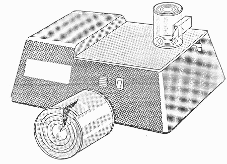
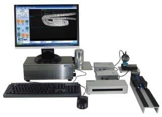
The projectors used to control the closures are of the type shown in figure no. 38 or similar.
Figure 38: Lock projector
In this equipment it is possible to take direct values of the hook lengths, by means of a suitable positioning of the fastener, by means of the reading that the mobile arms give us in the graduated ruler. See figure nº 39.
Figure no. 39: Taking measurements of a fastener on the projector
The hook must be positioned on the device in such a way that a clear image is obtained on the screen.
Body hook penetration
This is a critical parameter and we refer to what we will deal with in the section “ACCEPTABILITY OF CLOSURE”.
Overlap
This is a critical parameter and we refer to what we will deal with in the section “ACCEPTABILITY OF CLOSURE”.
9.- CHECKING OF INTERNAL DEFECTS OF THE SEAL
A good indication of the closing pressure is the impression produced on the inside of the body by the pressure exerted by the closing rollers on the mandrel. This indication alone is no guarantee of adequate sealing pressure.
One way to improve the grip of the mandrel is to knurl the surface of the mandrel lip, but this practice is not recommended, as it damages the protective varnish on the bottom in this area. It is always best to use a smooth mandrel and ensure that it is properly adjusted to ensure a good hold.
Let’s go into the description of the main visual defects that can occur in a disassembled fastener:
1º.- Fall in the union
It is the presence of a ripple, more or less important, on the inner side of the bottom hook, in the area of the side seam. The cause of the corrugation at this point is due to the higher pressure that is generated there, due to the greater number of layers of tinplate in it. See figure nº 40
Figure no. 40: Falling at the joint
In the case of containers with a crimped – or seamed – side seam, with or without side cement in the seam, this corrugation will be considerably greater due to the metal layers that form the crimp in this area.
The inside of the hook must therefore be examined and a value assigned to it as “drop at the joint” according to a reference scale or by measurement.
The “inner joint drop” must not exceed 50% of the bottom hook length. A 50% drop produces an overlap in the joint area of only 20% of the normal value.
It is also advisable to carefully examine the inside of the bottom hook on both sides of the assembly to detect irregularities, roller jumps, etc.
2º.- Footprint of the lip of the mandrel
It is the impression produced in the internal part of the body as a reaction to the double closure. See figure 41. It is the result of the pressure exerted by the second operation rollers during closing.
Visual inspection, together with other factors, allows us to assess whether the fastener is correctly tightened. Its total absence indicates lack of tightness, even if other measurements are correct. It shall have a light, uniform, clearly visible, clearly visible matte appearance, free of irregularities and always around the inside of the body at the closure.
An excessive footprint, a marked step, is an indication that the rollers or mandrel used may be wrong, or that the clamping operation has been performed with too much pressure. A mandrel that is too large will logically produce an excessive mandrel footprint.
Figure no. 41: Footprint of the mandrel lip on the body hook
It is a good indication of the closing pressure but does not guarantee that it was correct, so it should be used in conjunction with other inspections.
3º.- Visual inspection of wrinkles, undulations and other irregularities in the hooks of the body and/or bottom.
All these irregularities are produced by a lack of adjustment in the tooling, or because the tooling is not suitable, and can be of many different types. Among others are:
– Body tab with wrinkles
– Container slippage
– Small mandrel diameter
– Inclined chuck
– Rulina of 2nd loose operation
– 2nd operation roller profile worn out
– Clearance of the 2nd operation roller on its shaft
– other other
4TH PHASE: LEAKS
LEAK DETECTION
Independently of the analysis of the closure due to its destruction, it is necessary to verify in other complementary samples, the absence of leaks and therefore the adequate tightness of the containers. The quantity to be tested will be taken according to a predetermined sampling type, with the help of the corresponding tables, depending on the size of the lot and the quality level chosen.
The procedures to be applied vary depending on whether the can is empty or full.
a.- Empty canister
Pressurised air is used in two possible variants.
1ª.- By means of a head, pressurized air is supplied inside the container, applying at the same time, with the help of a brush, soapy water on the closures. If air leaks through the closures, bubbles will form at the exact point of the leak.
2ª.- Completely submerge the container in a tank with water, and apply pressurised air inside by means of an appropriate head. If the seal is defective or has pores, bubbling occurs due to the air escaping through the pores.
The air pressure used in both cases is of the order of 1.5 Kg/cm2 for containers with electrically welded side seams and size equal to or less than 1 Kg. For larger sizes or cemented seam is lower.
These procedures are used to sample batches, but other techniques are used on container production lines to check 100% of production for leak tightness.
b.- Full can or can closed at both ends.
There are complex procedures at laboratory level, such as the Lefebvre method, which requires a certain specialization. There are also simpler procedures such as the one indicated in our work on this website:
Manual container tightness tester
– Click here to access the 3rd part of this work.








0 Comments