INTRODUCTION
In most food packaging, the air inside the container is removed after filling. The aim is the suppression of oxygen, origin of different processes of degeneration of the content. An effective way of removing this air is to generate a vacuum in the free space (headspace of the container). There are several ways to achieve this emptiness. Such as:
– Fill to full (no headspace) and hot. When the product cools down, it shrinks and a vacuum chamber is obtained.
– Inject steam into the head space. It displaces the air and when it condenses, when it cools down, the same effect is generated.
– By means of mechanical vacuum. For this purpose, the container must be sealed in a closed, airtight receptacle in which an appropriate vacuum is created, thus also inside the container, and then sealed.
We will focus on the latter case.
The seaming machines prepared for this task have the seaming head integrated in a hermetic enclosure, as we have already said, connected to a vacuum pump. Once the container to be closed, filled with product, has been placed in the closing position, the pump is activated and a vacuum is generated in the chamber. Once it has reached the desired value, the closing is carried out. This process is slow, so production is low and equipment is expensive. It is only justified for products of high market value. Typical examples are infant formula, coffee or certain meat products. In many cases, an inert gas, e.g. nitrogen, is injected after the vacuum has been created in order to maintain a certain pressure inside the packaging in an inactive atmosphere.
In order to achieve a vacuum in the headspace of the filled container, it is necessary to allow the air trapped in the container to escape easily. The lid is already in the pre-closing position, i.e. with the flange of the lid resting on the flange of the container. This arrangement can hinder the extraction of air as the lid is acting as a shutter. The flange of the lid fits over the flange of the container body along two circumferences: a) The first defined by the edge of the flange at its contact with the rubberised area of the wing. B) The second determined by the fit of the lid bowl wall to the base of the flange. Therefore, it is necessary to lift the cover slightly so that a groove is created between the flange and the flange.
This effect is achieved by making a series of notches on the wing. These notches are the ones that rest on the flange, leaving the rest of the wing periphery elevated and therefore with free passage for the exit of air from the headspace. These notches are called “dimples”, a designation that is also used in the Spanish-speaking industry.
We now enter into the basic motif of this work, which focuses on the different types of (“simple”) notches that can be used and how to make them.
CIRCULAR NOTCHES IN THE CENTER OF THE LID FLANGE
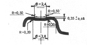
In the centre of the flange, a series of small circular inlays are made, approximately 0.35 mm. deep and 2.4 in diameter. Their number depends on the diameter of the cap, but in any case a minimum of 6 to 60º for caps with a diameter of less than 100 mm and from 8 to 45º for caps larger than this value. See drawing nº 1. Therefore, on the inner side of the wing there are a series of projections, which although the application of the rubber seal softens their relief somewhat, they are clearly noticeable.
Drawing No. 1: Dimensions of a notch on the flange of the lid
When the lid is placed on the flange of the container prior to closing, these raised dots are the ones that rest on the end of the flange. Therefore the flange of the lid is slightly raised above the lid. In this way it is possible to extract the air contained in the head space, producing the corresponding vacuum.
To assist in this function, it is advisable that the flange of the container is well inclined, at least 7º 30′, so that the contact between the notches and the flange is punctual, just at the end of the latter. Thus, the obstacle to the air outlet will be minimal.
These notches are made during the die-cutting of the lid. In order to do this, the following contributions must be made on the die:
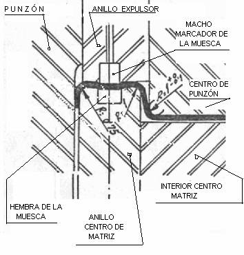
– Die center ring” (fixed lower part of the die): Make a series of lodgings that will act as a female in the die.
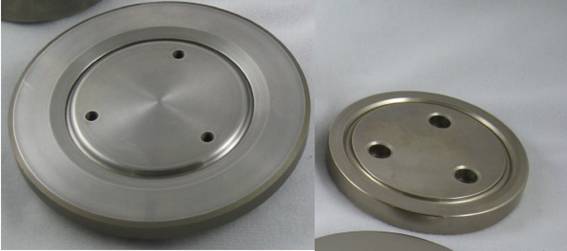
– Ejector ring (movable upper part of the die): Mount the same number of small cores. See drawing nº 2. This part must also be fitted with a guide system to ensure that it does not rotate or shift.
Drawing No. 2: Detail on a die of notch forming parts
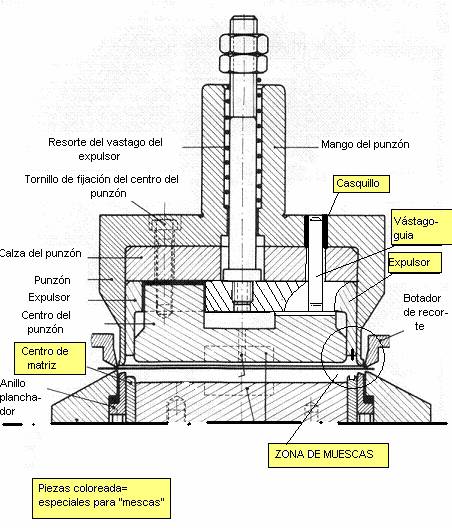
The “ejector ring” is a part that under normal conditions maintains a certain clearance to facilitate its movement inside the die. But in this case, being the carrier of the males to mark the points on the wing, it is necessary to ensure their exact positioning. Therefore, a pair of guide rods must be added. See drawing nº 3
Drawing No. 3: Modified ejector die with guide pins
This system of generating the notches has the advantage of a proven reliability, because even if they have little relief, when resting on the edge of the flange of the container, they guarantee an exit channel. On the other hand, it has the disadvantage, compared to other systems, of being quite complex in the preparation of the die. The realization of the set of male-female pairs is a task that requires a lot of precision. Also the smallness of the taps makes it easy to damage them during the working of the die.
HALF-ROUND NOTCHES IN THE WIDTH OF THE FLANGE
Half-round notches are made across the entire width of the flange, in a number similar to the previous case – between 6 and 8, depending on the diameter – and symmetrically distributed. The depth of the notches is usually 0.35 mm, i.e. the same as for circular notches. Its width is about 3 to 3.5 mm. See drawing nº 4. In this way, radial ribs appear on the inner side of the flange, which emerge on the closing compound. They perform a function analogous to the case of the circular grimaces in terms of the action of making the vacuum.
The recommendation regarding the angle of inclination of the flange also applies here.
Drawing No. 4: Position of a half-round notch on the flange of a lid
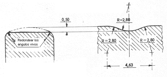
To make these “simple”, it is enough to machine in the upper part of the “die centre ring”, the corresponding grooves. Its dimensions are shown in drawing no. 5. There is no need to mount any kind of tap on the “ejector ring”, as the tinplate copies the shape of the carcass during the drawing of the cap.
Drawing No. 5: Machining of the top of the centre ring matrix
This way of forming the vacuum notches has the advantage of simplicity in the preparation of the tooling. Only one part is affected and therefore there is no difficulty in aligning with other parts. The die is uncomplicated and maintains its robustness. On the other hand, the main disadvantage detected with this “simple” system is in the closing of the container. The curl of the lid in the areas of the notches, has a greater height, which is logical because there is less deformation at these points -lower bowl height-. Depending on the type of seamer, these differences in curl height on the same lid can cause difficulties in feeding and even problems in the quality of the seal.
NOTCHES ON THE INNER ARC OF THE FLANGE OF THE LID
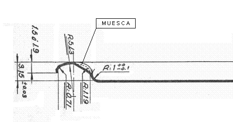
In this case the notches are made in the arc that joins the flange with the lid bowl, i.e. on the inner radius of the flange. They have a sloping half-round shape. Its depth is 0.6 mm. and its length 1.5 mm approx, both averages in its inclined position. In the drawing nº 6 you can see its position. Their number can vary from 6 to 16, depending on the diameter of the lid. With this type of notches, unlike the previous ones, the support on the flange is made on the radius of the flange, instead of on its edge. Therefore the final angle of the flange is not very important.
Drawing No. 6: Positioning of notches in the inner arch of the wing
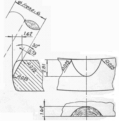
Similar to the previous system, the preparation of the die for its realization, is focused on the realization on the “die center ring” of some machining with the appropriate inclination and measures. Drawing nº 7 shows them.
Drawing No. 7: Detail of the preparation of the “matrix centre ring”.
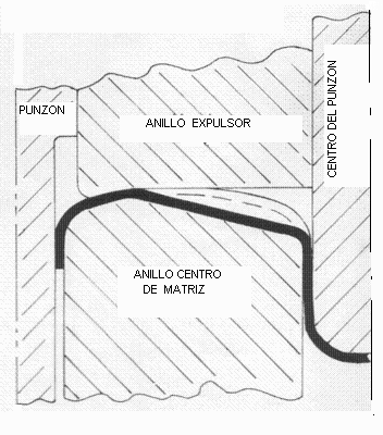
In the drawing nº 8 you can see how the tool works and how the notch is formed.
The advantage of this type of “simple” is, like the previous one, the ease in the preparation of the die, because it is again a single piece – die center ring – which must be suitable. Therefore its simplicity and strength are assured. There are no significant disadvantages. Only visually, slight marks can be seen on the wall of the flask after closing. The seamer must also be robust to provide the extra effort required to crush these notches.
PACKAGING PREPARATION
In order to achieve optimum results with any of the types of notches described in the previous points, it is also advisable to adapt the body of the container to the use of lids with this type of notch.
The actions to be taken on the bodies are as follows:
– 1.- As we have already indicated above, it is convenient that the flange of the container is well inclined, at least 7º 30′, so that the contact between the notches and the flange is punctual, just at the end of the latter. Thus, the obstacle to the air outlet will be minimal.
– 2.- It is normal for the lid to fit slightly tightly on the body. Good practice advises that the diameter of the cap should be approx. 0.20 mm. larger than that inside the body (although this value is a function of the size of the container). However, in containers that are going to be mechanically vacuum sealed, using notches, this adjustment must be the opposite, i.e. there must be a clearance between the lid and the body of the container. The diameter of the body should be approx. 0.30 mm larger than the diameter of the lid. The reason for this is to prevent the lid from acting as a shutter, allowing air to escape between the two. This does not mean that you have to give more material to the development of the body to obtain a larger diameter. The same cylinder development dimension is used as in a normal case, and therefore also the same diameter initially. Its enlargement is achieved by enlarging the diameter of the flanging tool – tampon – by this amount, and thus flaring the body at its end during the flanging operation.
– 3.- In some cases, slits are used in the body flange as a complement to the “simple” ones. These indentations have a depth of 1 to 1.5 mm and a rounded profile. They are positioned radially. They are performed in the flanging operation by modifying the flanging pad accordingly. Their number must always be different from that of the “simple” ones so that when the lid is placed on the container they never coincide with each other. This solution can replace the one proposed in nº 2, as it achieves the same effect of making the fit between the cover and the body not airtight.







0 Comments