
 SUMMARY
Packaging manufacturers have contributed their experience in improving the equipment that the market offers. In the case of body welders, this has also been the case. This reflects the improvements incorporated into the circuit of copper wire in these machines.
BACKGROUND
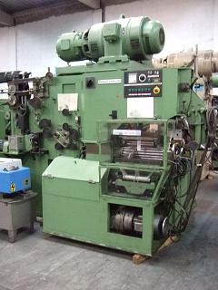
Modern welders have a fairly well designed copper wire circuit, which usually does not present problems. This is not the case with the first generation automatic machines – from the “70s” and “80s” of the last century – many of them, more or less updated, are still in operation. In many models, such as Soudronic SBW, ABM or FBB, the original copper wire circuits caused certain quality limitations in the welding of the container body.
They were the manufacturers of packaging, which based on experiences in the manufacturing process, which gradually introduced significant improvements in them, in order to eliminate quality problems. Among these manufacturers stood out the team of experts from Carnaud-France, who were among the first to contribute significant progress in the technique of the soldier, focusing on automatic machines with a certain production rate. Among these experts he highlighted the good “know-how” of Claude Renard, who contributed considerable advances to this technique. The present work is the result of your knowledge.
The welding machines are long life machines, because by their design and operation there are not many parts in them subjected to movement, and therefore to friction and wear. Therefore, with proper maintenance, they can remain “active” for many years. Nowadays this is the case with the aforementioned models, and many units maintain their original design, therefore the improvements that we will indicate have not lost their relevance.
IMPROVEMENTS IN THE COPPER THREAD CIRCUIT
The first circuits of the mentioned machines had the disadvantage of excessive heating of the electrodes, that is to say of the wire. This generated a series of problems on the container and on the machine as they were:
– Presence of projections inside the container, caused by expulsion of molten metal outside the weld.
– Leaking leaks, caused by breakage of the flange in the weld area.
– Excessive heating of certain parts of the machine, such as the wire circuit, welding arm, sheaves, crown …
– Too much heat in the welded seam of the container, which caused it to break in the tear test.
– Short life of welding sheaves.
Before continuing reading this article, we recommend that the uninitiated read the following works published on this website:
– Electric welding
– “Commas” in welding and its micrographic control
– Copper wire
Their assimilation will allow them to follow without difficulty the comments that we will make next.
The improvements introduced in the circuit were basically two:
1º.- Change the sequence in the same route. For example in the case of the welding machine type FBB, in the original version of the machine, it was first passed through the upper (outer) sheave and later the lower (inner) sheave. See figure nº 1.
SUMMARY
Packaging manufacturers have contributed their experience in improving the equipment that the market offers. In the case of body welders, this has also been the case. This reflects the improvements incorporated into the circuit of copper wire in these machines.
BACKGROUND
Modern welders have a fairly well designed copper wire circuit, which usually does not present problems. This is not the case with the first generation automatic machines – from the “70s” and “80s” of the last century – many of them, more or less updated, are still in operation. In many models, such as Soudronic SBW, ABM or FBB, the original copper wire circuits caused certain quality limitations in the welding of the container body.
They were the manufacturers of packaging, which based on experiences in the manufacturing process, which gradually introduced significant improvements in them, in order to eliminate quality problems. Among these manufacturers stood out the team of experts from Carnaud-France, who were among the first to contribute significant progress in the technique of the soldier, focusing on automatic machines with a certain production rate. Among these experts he highlighted the good “know-how” of Claude Renard, who contributed considerable advances to this technique. The present work is the result of your knowledge.
The welding machines are long life machines, because by their design and operation there are not many parts in them subjected to movement, and therefore to friction and wear. Therefore, with proper maintenance, they can remain “active” for many years. Nowadays this is the case with the aforementioned models, and many units maintain their original design, therefore the improvements that we will indicate have not lost their relevance.
IMPROVEMENTS IN THE COPPER THREAD CIRCUIT
The first circuits of the mentioned machines had the disadvantage of excessive heating of the electrodes, that is to say of the wire. This generated a series of problems on the container and on the machine as they were:
– Presence of projections inside the container, caused by expulsion of molten metal outside the weld.
– Leaking leaks, caused by breakage of the flange in the weld area.
– Excessive heating of certain parts of the machine, such as the wire circuit, welding arm, sheaves, crown …
– Too much heat in the welded seam of the container, which caused it to break in the tear test.
– Short life of welding sheaves.
Before continuing reading this article, we recommend that the uninitiated read the following works published on this website:
– Electric welding
– “Commas” in welding and its micrographic control
– Copper wire
Their assimilation will allow them to follow without difficulty the comments that we will make next.
The improvements introduced in the circuit were basically two:
1º.- Change the sequence in the same route. For example in the case of the welding machine type FBB, in the original version of the machine, it was first passed through the upper (outer) sheave and later the lower (inner) sheave. See figure nº 1.
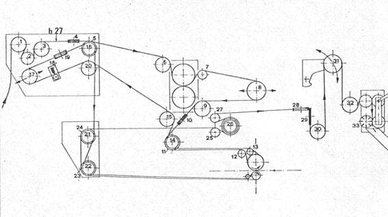
Figure No. 1: Original copper wire circuit in a Soudronic FBB welding machine
On the contrary, in the modified circuit, the order was reversed, passing before the lower one. See figure No. 2. The explanation for this change is that the lower sheave is more critical and delicate than the upper sheave for several reasons: – Its smaller size makes the heat dissipate worse, heating up excessively. – It cools worse, due to its difficulty of ventilation and access, being mounted inside the welding arm. – It wears out more because it has a smaller diameter and therefore gives more number of revolutions per unit of time. All this affects the quality of the welding. It is therefore convenient that the yarn reaches this sheave as cold as possible, and in the best mechanical conditions. This is achieved by giving preference to the arrival of the thread, as it will only receive the contribution of heat generated by its profiling.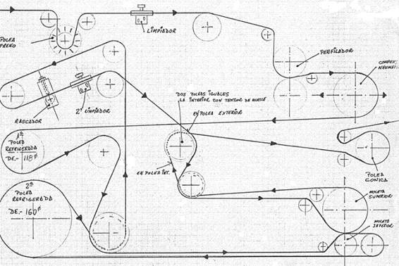
Figure No. 2: Modified copper wire circuit in a Soudronic FBB welding machine
2º.- Incorporate a refrigerated pulley of large diameter at the exit of the lower sheave. As can be seen in figure 2, the wire circulates, embracing almost entirely a second pulley with a diameter of 160 mm, greater than the first with a diameter of 118 mm. As can be seen in the diagram, the pulley cooling of 118 mm acts on the yarn after profiling it, and before entering the lower sheave. The 160 mm operates on the thread after leaving the lower sheave. This achieves a very strong cooling of the yarn, which implies a drop in temperature during the rest of its trajectory. The following table compares yarn temperatures throughout its course, in its original version and in the modified one with a change of sequence and an added refrigerated pulley. Control point Original circuit. Inverted circuit A pulley cooler. Two pulleys refriger. Thread entry without profiling (Ambient Temp) 24 ºC 24º C Profiling outlet 52º C 52º C Refrigerated pulley entry dia. 118 mm 52º C Exit “” “” 32ª C Input weld lower weld 52º C 32º C Exit “” “265º C 240º C Refrigerated pulley entry dia. 160 mm 240º C Output “” “” 80º C Roldana entrance weld superior 245º C 98º C Output weld upper welding 185º C 91º C In the second case you can see the drop in temperatures at the entrance of both welding rollers compared to the first. The pulley cooled of diameter 118 mm. it lowers the temperature from 52 to 32º C and that from 160 from 240 to 80º C. These modifications generate the following advantages: a.- Cancel the projections. It is the main one; the inner part of the welding remains without projections and therefore without exposed metal. b.- Avoid leaks. Practically the problem of cracked eyelashes disappears, even with sheets of high coatings. c.- Constant temperature. Before putting these improvements in gear, as the working day progressed, it was necessary to increase the value of the fine current potentiometer, at least in 2 or 3 divisions. Then the same adjustment is maintained. d.- Solder with less energy. With this modification it is observed that the potentiometer can be adjusted lower than before, with an estimated saving of energy equivalent to 3 divisions of its scale. e.- Lengthens the life of the sheaves. The average life of the lower sheave almost doubles and the upper one increases by 40%. All these improvements have the same origin: The weld bead has much less temperature than before, especially for its internal face. Therefore it gives it a greater elasticity. This is checked through the tear test. In the original conditions of the machine, almost always there was a break in the welding in this test, and in the new ones it is totally complete. There is the possibility of a third improvement, and that is to pass the thread through the outer welding wheel – upper – in the same position as in the lower one. That is to say, presenting to the weld the same side of its elliptical profile, and therefore the same contact face it had with the lower weld sheave. This is achieved by rotating 180 ° is thread, ie twisting half turn, after passing through the scraper and 2nd cleaner and before reaching the upper welding sheave – or milling wheel -. The objective of this change is to lengthen the life of the upper sheave, by always presenting on it a surface of clean thread and without contamination of tin, avoiding the abrasive effect on its throat. The increase in the life of the upper wheel is remarkable, although it shows the other contaminated face of the thread again, since it is the one used in the contact with the tin plate as it passes through the lower wheel – it contributes slight imperfections to it by its exterior. However, welding on its external face is always less critical than on its internal face. This third improvement, has opposing opinions, because some people think it is not a great advantage. It is about testing in each case and personally evaluating the results.


0 Comments