
Importance of the bead in a metal cans, different types, their design and uses, as well as the technique to carry them out with their various models of equipment.
INTRODUCTION
In a package, bead is understood as ribs positioned parallel to each other, and usually perpendicular to the axis of the body thereof.
The use of beads or refrains on packaging is a relatively recent contribution compared to the long life of the cans in the market. It was a consequence of the use of thinner tinplate and with greater hardness.
The need to lower the cost of a can, reducing the consumption of basic raw materials, tinplate, caused the appearance on the market of new types of material, of less thickness and greater temper. This was possible, thanks to the contribution of substantial improvements by the steel industry, such as electrolytic tinplate, or steel obtained by continuous casting.
During its useful life, the can is subjected to a series of mechanical stresses, which must be overcome by means of adequate radial and axial resistance. The axial resistance allows its stacking at high heights, and the radial resistance absorbs the actions of an internal vacuum or overpressure, which originate fundamentally during its thermal process in the canning plants.
The reduction in thickness of its walls did not decisively influence its axial resistance, but it considerably reduced the radial, resulting in frequent problems of “sucking” or collapsing of its walls, due to the presence of internal vacuum. This was solved with the incorporation of cords in the cylindrical bodies of the containers.
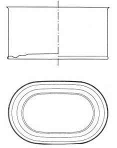
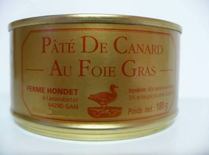
In the canning industry, the use of bass strings is widespread in cylindrical containers, both of the “three-piece” type, as in deep sausages (sausages-re-packaged), although it is not necessary in low-level cans, as they are sufficiently resistant . In relation to non-round containers (rectangular, oval, trapezoidal …) and of certain height, there is no significant consumption in this sector, since its use is limited to meat products. In this case if it is necessary to reinforce the side walls, it is used to “decode” them with geometric shapes.
DESIGN
In the metal industry various types of cords are used. One of the others are differentiated by their shape or geometry and by their location.
Geometry : Usually two different types are used:
A.- With a section in rounded shape, almost semicircular. See figure nº 1. Its complete profile is a succession of arcs of circumference, not presenting flat parts.
Figure nº 1: Rounded laces
They are used when you want to improve the rigidity of the wall and a good radial resistance.
B.- Angular, almost obtuse angle, with its apex rounded with a small radius. See Figure No. 2. Therefore, each cord has two flat faces, topped by an arc of a circle.
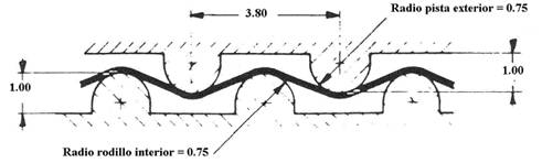
Figure nº 2: Angled cords
They give greater elasticity to the wall and maintain a good radial / axial resistance ratio.
Location : The laces can be positioned on the wall of the container body in three different ways:
A.- With separate cords, ie keeping each cord a certain distance from the nearest. This distance is always several times greater than the width of the cord. Along the height of the container, a series of them are distributed, maintaining a constant step between them. See figure nº 3.
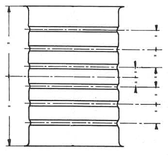
Figure nº 3: Container with separate laces
This distribution is usually combined with rounded cords and is used mainly in large formats of containers, for example in diameters 153, 230, etc.
B.- Forming compact blocks, centered on their height and occupying most of it. The passage between cords coincides with its width, so there are no straight parts on the wall of the container, except at the ends thereof. Normally angular cords are used in this case. See figure nº 4.
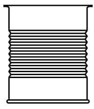
Figure nº 4: Packaging cordoned with compact blocks
They are generally used in small formats, from 52 to 99 mm in diameter. When the height allows it, there are usually up to 15 or more cords in a row.
C.- Mixed, that is, a combination of the two previous cases. Two groups of laces are positioned, with a straight section in the center of the height. Each group commonly has three to five cords. See figure nº 5.
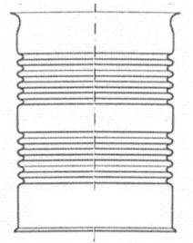
Figure nº 5: Container with mixed cordoning
It is difficult to determine which is the ideal cord type. Each boat requires an adequate study, before defining the cord design to apply on it. The correct cord is a function of:
– The diameter and height of the container
– Use of it
– Conditions of use.
It is very difficult to implement the use of different cords based on these three factors. In fact, it is determined which is the most favorable cord type for the most general use in each format, and this type of cord is applied in all cases. It is economically impossible to change tools to cordon each different use.
On the other hand, although very deep studies have been carried out with simulation programs, there have not been very marked differences in the performance of the different types of cords, and most of them provide acceptable results.
All the previous cords are positioned parallel to the base of the container, but there are manufacturers who use cords in the form of a propeller. It is a minority application with little experience in the market.
TEAMS
The refrains are made in specialized machines, called cordoners or beading. The primitives consisted of two rollers that carried the male and female silhouette respectively of the bead. The body of the container was introduced into the lower one – female -. When the cycle started, the rollers approached and turned in the opposite direction, marking the cords. Figure 6 shows a photo of this original type of cordon, which is still used for small series, since the feeding is manual.
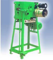
Figure nº 6: Manual beader machine
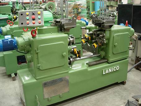
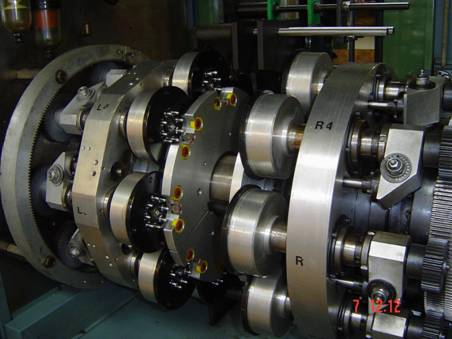
Subsequently modified the machine concept, to do the automatic process. A new generation of equipment was designed, which worked with the axis of the cans in a horizontal position, hence its name to horizontal beader machine. See photo nº 7.
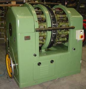
Figure nº 7: Horizontal 12-arm cord
These machines have a series of opposite pairs of arms, with alternative opening and closing movement, driven by cams, which in turn rotate on their own axis. The number of pairs of arms depends on the desired speed of production. The normal thing is to have twelve. A mandrel or roller is mounted on each arm, with the internal silhouette of half the number of cords to be made. See figure No. 8. The diameter of the mandrel is always lower than that of the body of the can to be beader.
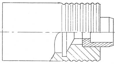
Figure nº 8: Male mandrel, with the drawing of the half of laces to form
When a pair of arms separates, it allows the feeding and positioning of a body between them. When the pair of arms meet, the complete profile of the bead is formed. To align them correctly, they have a male-female insert at their contact end. Figure 9 shows different types of rollers.
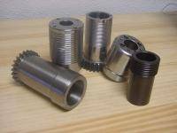
Figure nº 9: Different types of cord wrappers
Each pair of male-female mandrels, introduced inside the body of the can, in its turn force the body to rotate on an external track. This track is a circular sector in the form of a rim, which on its outer side reproduces the shape of the bead. In drawing no. 10 a partial detail of the section of a lacing sector is appreciated.
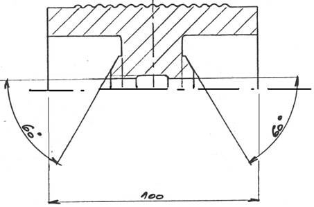
Figure nº 10: Detail of the section of a lacing sector for 15 laces
As we have already said, the rotation of the rollers rotates the body of the cans on the track, copying the silhouette of the cords. The greater or lesser depth thereof is achieved by adjusting the approximation of each roller to the track. Due to the elasticity of the tinplate, although the tooling is perfectly done, with all the bends equal and of the same depth, the result on the body is that the beaders of the center are shallower than those of the ends, next to the bases of the can.
To improve this effect, the profiles of the staffs are machined with an increasing height from the ends to the center, giving each bead 0.02 mm more height than its contiguous, reaching the maximum in the center. Therefore, in the case of the drawing, the machining radius of the central bead would be 0.14 mm greater than that of the ends. With this compensation, cords of the same depth are obtained on the package.
The surface finish of the tooling in its active areas – in contact with the tinplate – must be very good, otherwise it could damage the interior varnish. Therefore, both the rollers and the track must be made of treated and polished tool steel. It is even better to add a superficial industrial chrome treatment in the work areas.
There are two versions of horizontal beading machines according to the design of the sector or beader track. A first type more frequent, in which the track presents the moldings of work in his external face, as it is indicated in the figure nº 10. In this case the sector has a lower radius to the one of the displacement of the arms, that is to say the arms they move externally to the sector. An example of this type of machine is shown in photo No. 7. A second type is just the opposite, in the same sector is the outermost piece and the working moldings go on its internal side, this second case is less used.
With the appearance of modular lines, a new generation of beaders emerged, which although working with the same principle, the whole system is mounted so that the package moves in a vertical position. In photo # 11 you can see an example of them.
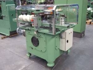
Figure nº 11: Vertical beader machine
In either type, the container bodies are fed and extracted from the machine by means of spindles and stars. During their journey through the machine, they are controlled by external guides.
It is increasingly common that this equipment is part of a modular machine, consisting of different modules, each performing a different operation, such as: separate, notched, flanged, cordoned …, with this you get very compact.
 RELATIONSHIP OF HEIGHTS IN MANUFACTURE OF AEROSOL CANS
 MECHANICAL PROPERTIES OF CANS
 GUARD BEAD TOOLS
 PRODUCT TECHNICAL SHEET: CANS “THREE PIECES”
 TANNING
 ENTAILED PACKAGING
 CONTAINERS FOR SAUSED PACKAGING
 PACKAGING TWO PIECES DRD
 OVERHEADS AND PRESSURE PLUGS FOR METAL CONTAINERS
 DIMENSIONS FOR CUPPAGES OF ENERALED AEROSOLS


0 Comments