SUMMARY
Study of the characteristics, dimensions and equipment necessary for the manufacture of domes of aerosol containers.
INTRODUCTION
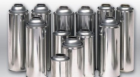
The aerosol containers are part of our life, during a certain day we are sure to make use of them several times. Its fields of application are multiple: personal hygiene, perfumery, household cleaning, gardening, industrial uses, health … There are metallic – tin or aluminum – and glass. The most widely used are the first in its tinplate version.
The aerosol container is characterized by having a dome-shaped top cover that fulfills several functions:
– Present a high resistance to internal pressure
– Serve as a support for the dosing valve
– Use as an anchor the plastic cap
– Give an aesthetically pleasing configuration to the set.
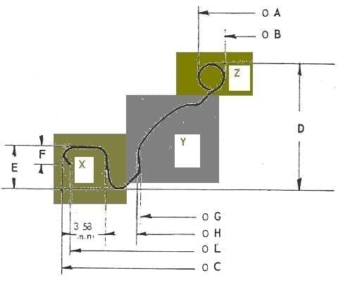
This dome lid also receives the name of cone and in it the following parts are distinguished:
– X.-Closing area, comprising the wing and the bucket, similar to those of a conventional lid. It serves to make the closure – union – with the body. The plastic plug is hooked on itself
– Y.-Dome itself, which gives adequate resistance to internal pressure
– Z.-One inch diameter center hole – 25.4 mm – for valve housing.
See figure # 1:
Figure nº 1: Areas of the dome
In this work we will describe the specifications of raw materials and the manufacturing process of these domes, focusing exclusively on aerosol cans of tin.
SPECIFICATIONS
The aerosol containers made in tinplate by the technique “3 pieces”, are formed by a cylindrical body, a bottom and a dome. Nowadays, almost all of them are made of the fitted type, that is, with both ends reduced. The most common diameters are:
BODY FUND CUPULA
45 42 41
49 47 45
52 50 48
57 54 52
65 63 60
That is, there are five different diameters of domes on the market. The reason for which the diameter of the same is smaller than the one of the bottom of the container, is so that once placed the plastic stopper on the dome, the external diameter of the set is equal in all the zones of the container.
The specifications of the different cone diameters differ from each other. Let’s see the most important ones:
Tinplate : Tinplate tinplate under E 2,8 / 2,8 is used for its manufacture, since it is always used on both sides. The temper, due to its certain level of drawing, must be low; the T – 57 gives good results. The thicknesses are linked to the diameter. As guide values can be taken:
CONE THICKNESS (mm)
41 0.28 – 0.30
45 0.28 – 0.30
48 0.29 – 0.31
52 0.30 – 0.32
60 0.33 – 0.35
Varnishing :
Exterior : Three alternatives are used, white, gold and colorless.
White :
1st pass epoxy coupling varnish (film weight approx.1.2 gr / m2)
2nd pass Acrylic white varnish (film weight approx 13 gr / m2)
Lithography Texts or other simple decoration can be printed, always in the lower part of the dome, where the deformation during embossing is less
3rd pass Epoxy finish varnish (film weight approx. 4 gr / m2)
Golden:
Single pass Golden epoxy-phenolic varnish (film weight approx 6.5 gr / m2)
Colorless:
Single pass Clear epoxy-urea varnish (film weight approx 5.5 gr / m2)
Interior: It can always be golden
1st pass Golden epoxy-phenolic varnish (film weight approx 5.5 gr / m2)
2nd pass Golden epoxy-phenolic varnish (film weight approx 5.5 gr / m2)
Paraffin :
Tin packs once varnished must be lubricated with paraffin on both sides of the sheet to support the embossing operation well. This is done in a paraffin-filler that applies a thin layer of molten wax by means of spray nozzles that work with pressurized air. The appropriate load to apply is 0.14 g / m2 + 0.4.
Cut:
Depending on the equipment available for manufacturing, the sheets are cut into scored strips to be punched in single, double or multiple tool. The most normal case is double strip to feed the press of 1st operation – or stuffing – which in turn will provide parts to the transfer presses.
Manufacturing operations :
The domes are configured progressively, in several operations, from the flat strips of material. The number of steps varies depending on the design of the same and its size. The most normal thing is that it takes place in about 7 or 8 phases, of which the first one is the making of a sketch embedded in the press, the next 5 or 6 – made on transfer – give shape to the dome and the last ripple on the edge. Subsequently, the wing is gummed. Figure 2 shows the complete cycle in all its operations.
Figure nº 2: Sequence of manufacture of a dome
To follow step by step each of these phases we will take a concrete example of dome. We have chosen the nominal diameter 48 mm because they are the most used in the market.
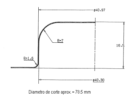
1st operation :
It is carried out as we have already indicated on a conventional automatic press for the manufacture of covers, fed with bands. It involves stuffing a metal cup, which serves as a sketch, with enough material to configure the dome with the necessary stuffing that it will demand. Figure 3 presents a possible design of this phase.
Figure No. 3: 1st day dome operation. 48
2nd operation:
It is usually the first performed on a transfer press. In it the cone tray is formed – with what the nominal measurement of the cone is defined -, in addition, the dome shape of the piece and the assembly area of the valve are initiated. It has a certain resemblance to a hat. See figure nº 4.
Figure No. 4: 2nd day dome operation. 48
3rd operation
Next operation on the transfer, in which the dome area is completed and the embossing of the upper “chimney” that will lead to the location of the valve is completed. The area of the tray does not change. In this operation, the maximum drawing is achieved. See drawing nº 5.
Figure nº 5: 3rd day dome operation. 48
4th operation
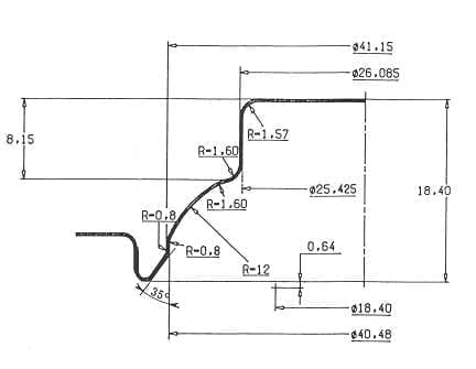
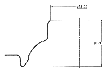
Third on the transfer, it has as purpose to make a hole in the upper horizontal part of the “chimney”. The same in our case has a diameter of 23.37 mm and is topped all around by a radius of 1.5 mm approx, which links to the vertical wall. The valve seat will be prepared from it. See figure No. 6. It is very important that the cut of this hole is made cleanly, without generating burrs on its edge.
Figure No. 6: 4th day dome operation. 48
The trimmed disc is removed by the bottom of the tool. To facilitate its exit, it is struck in the center of it at the moment of cutting so that it takes the shape of a bowl and thus reduce its diameter.
5th operation
Fourth on the transfer. In it, two actions are carried out:
- a) Trim externally the excess material that has remained irregularly in the outer wing of the piece. During the drawing, and following the direction of rolling of the steel, there has been an elongation of the grain, which is reflected in irregularities in the outer cutting edge. Irregularities that are eliminated when cutting this trim in the form of a ring. To evacuate this ring, the die of this operation is provided with small external blades that cut into several pieces, which fall on the sides of the press,
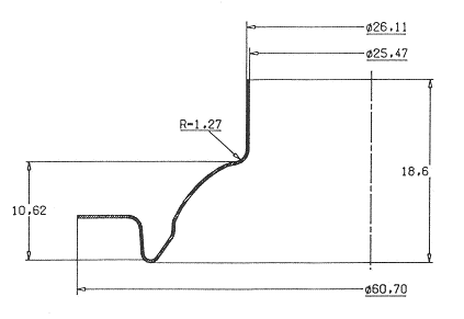
- b) Put vertical, iron and lightly laminate the edge of the inner cut to leave it ready for the next operation. This action is usually critical to allow a good posterior curling.
See figure # 7.
Figure nº 7: 5th day dome operation. 48
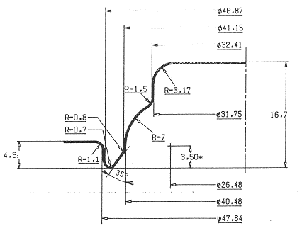
6th operation
It is the last step made on the transfer press. In him two actions are made:
- a) The outer wing of the dome, which until now has remained flat, is bent at 90º forming the external curl of the cone. It is an operation analogous to that performed on any metal container lid.
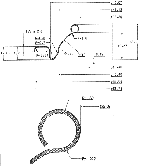
- b) The vertical wall of the “chimney” curls outward, forming a ring on which the diffuser valve will be mounted on the container filler plant. The hole that this ring delimits is standardized to the value of one inch (25.4 mm)
Figure 8 details the part as it comes out of the transfer press, once this operation has been carried out.
Figure nº 8 : 6th day dome operation. 48
7th operation
Mechanically, to give the cone as formed, it is only necessary to tilt the external curl inwards. This phase is carried out in a curling machine applied to the outlet of the transfer press. In the case of the dome 48 that we are following we would give an outside diameter of 57.80 mm with a curl height of 2.1 approx. The appropriate profile of the tool throat to make the cone curl is the one indicated in figure 9.
Figure nº 9: Profile for curling of domes
8th operation
It only remains to apply the compound on the inside of the wing in a glue mounted after the curling iron. The gum used is normally of the “water-based” type, with a high solids content, which only needs a baked garter belt for drying.
INSTALLATION FOR MANUFACTURE
Actually we have already listed each of the necessary machines in the description of the specifications of each stage of the manufacture of the domes. However now we will return to them, focusing more on the characteristics of the machines.
In the production of cones, two groups of equipment are required:
– Facilities commonly used for different applications:
- Cutting line for tin coils
- Varnishing and printing lines
- Paraffiners
- Scroll shears
For being generic equipment, of multiple applications we will not enter them for being well known.
– Specific facilities for the manufacture of domes
- Automatic eccentric press
- Transfer press
- Rizadora
- Engomadora
These equipment require special features that we will detail below.
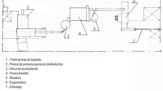
With all of them a cones manufacturing line is installed whose location can be like the one shown in figure # 10.
Figure nº 10: Implementation of a domes manufacturing line
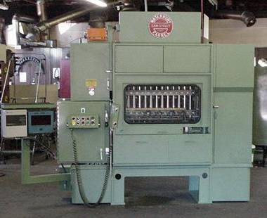
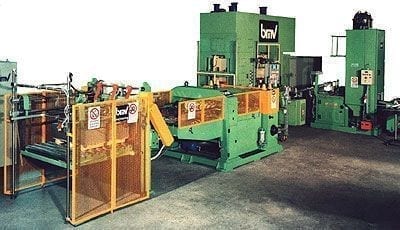
In photo no. 11, another possibility of installation is presented. In this case, the scroll shear is incorporated into the line with exclusive dedication – machine in first term – and the first operation press is dispensed, since it is performed on the transfer press fed directly from bands coming from the shear scroll . The transfer press appears in the center of the photo. At the bottom of it is the sticker.
Figure nº 11: Simplified installation of domes
1st operation press:
To carry out the 1st operation of drawing – as written above – the usual is to use an automatic press, gooseneck, equipped with feeder bands of material, the reasons for this are several:
– Being a fast team, with a single press you can feed parts to several transfers because they are much slower these last ones.
– Simplifies the characteristics of the necessary transfer presses. These second ones are expensive equipment and by not performing the embossing operation on them they reduce their need for power and the number of operations, thereby lowering the equipment.
This press of 1st operation must have a high stroke to allow the correct drawing and ejection of the piece, so it is not usually worth a standard press for manufacturing caps. It can work with double punch tool, which increases its capacity to supply several transfers.
Transfer
It is the basic machine of this installation. Fed from the press of 1st operation, with a lung of intermediate pieces to compensate for small stops, you must have at least 5 steps.
The basic characteristics of this press can be:
– Power 40 Tm
– No. of stations from 6 to 10
– Distance between stations 125 to 150 mm
– Carrera 130 mm
– Speed 100 to 140 strokes / minute
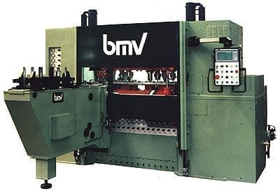
You can also choose to dispense with the press of first operation and directly feed the transfer of bands as already indicated. That solution can be good when production needs are covered by a single transfer press. Photo no. 12 presents a press with these characteristics, with a built-in strip magazine
Figure nº 12: Transfer press with strip magazine.
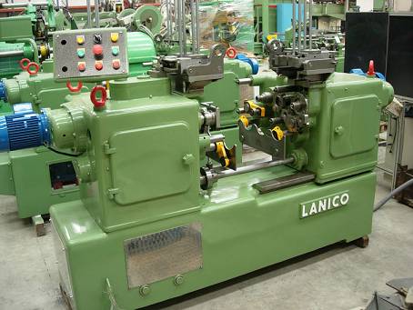
Rizadora
Located at the exit of the transfer press, it collects the production of the same by means of a fall by gravity. It does not require any particular characteristics.
Engomadora
This machine must be specially prepared, to allow working with elements of high height. Your warehouse, separation nails, power bars and plates are specific to domes. The same happens with the extraction furnace, where the up and down augers must be one step higher for the same reason.
If rubber with a high solids content is used, the drying time and temperature will be moderate.
Tools
The stamping should be of good quality. In it, the lower pressure systems are very important, which must be very well aligned and maintained.








0 Comments