
Some indications for the realization of the holes for lodging plastic necks in metal containers.
PREAMBLE
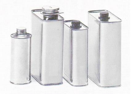
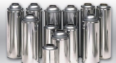
The use of plastic necks, spouts and stoppers is very widespread in metal containers intended to contain liquids such as edible oils, industrial products, etc. They facilitate the dumping of the same and the partial use of the product.
It is the metalworker’s job to prepare the lid of the container so that later said neck can be placed. For this, it is necessary to make a hole on said cover, in which the neck will be introduced. The assembly of the same on the container can be done at different times:
– In the loose lid, that is to say before being closed on the body of the container. In this case the assembly operation is carried out by the metalworker. The cover later can be:
- closed by the metal and then the packer will fill the bottom and close the same
- closed by the packer, once the container is filled. In this case the metalworker has previously closed the background.
– In the container once full. The can is supplied to the packer with the bottom and the lid placed. The filler fills it through the hole destined to the neck and later lodges the neck in it. In this option the packer will avoid closing the lid or bottom.
There are different ways to design the hole on the lid for the neck and in this article we will see some of them.
TYPES OF ACCOMMODATIONS
The way to fix the neck on the lid defines the type of hole or housing to be made on it. The most common ways to execute this operation are:
– Pressure: The neck / plug penetrates forced into the hole and remains in it forced by the neck-hole interaction.
– Seaming: A flange or flange of the neck is mechanically aggravated with the flange of the hole.
The variants of these two basic systems are many, and the possible means to employ as well. We will see some examples of them below.
1º.- FOR PRESSURE ASSEMBLY
The pressure-mounted necks are characterized in that they present, in the area where the lid meets, a throat where the skirt of the hole made on the lid is received with force, after passing over a projection that subsequently prevents its extraction. The neck rests firmly on the rim of the hole, by means of a projection located externally to the throat. Photo No. 1 presents an example of this type of neck
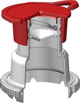
Figure No. 1: Snap-in fitting
Within this type of pressure mounting we can differentiate two varieties of holes:
1st.- Orifice “without burrs”:
An example of this first type is indicated in the drawing of figure 2:
Figure no. 2: Snap-fit installation of a neck without burrs
It is characterized by protecting the cutting edge of the hole, so that the packaged product can not easily contact it. It is used for aggressive packaging that could attack the steel seen at the cutting edge, for example for brake fluids. To achieve this, we use:
– Make a cut on the lid with the minimum possible burrs, hence its designation. In this way there is less exposed metal and above all the edge presents a smooth and uniform surface.
– Present the neck a very marked shoulder or step, where the edge of the hole is nailed, for its protection against chemical attacks.
Therefore both the diameter of the hole and the height of the skirt must be very precise and are critical measures.
We will present a concrete example of realization of the hole, noting that it should be taken only for the sake of an idea, as each manufacturer of necklaces should specifically indicate, for each type of their manufactured, the dimensions and ideal way to make the hole.
In this example the accommodation is done in two stages. The first one is simultaneous to the realization of the lid. That is to say, it is a question of providing, to the manufacturing die of the lid, the necessary pieces to form a circular groove, which prepares the part where in the next operation it will be made in hole.
Figure 3 shows an enlarged detail of the dimensions of this part of the lid needed to subsequently make a hole with a diameter of 23.8 mm
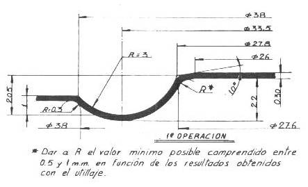
Figure no. 3: 1st operation on “no-burr” orifice lid die for pressure neck
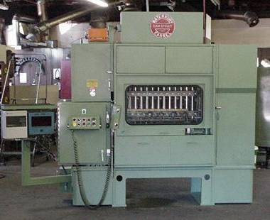
The second stage is carried out on another press, equipped with a lid feeder, on which a cutting and ironing tool is mounted, which makes the hole and correctly marks the silhouette of the housing.
In the following figure – No. 4 – appears the 2nd operation for drilling a hole with a diameter of 23.8 mm, continuation of the one initiated above.
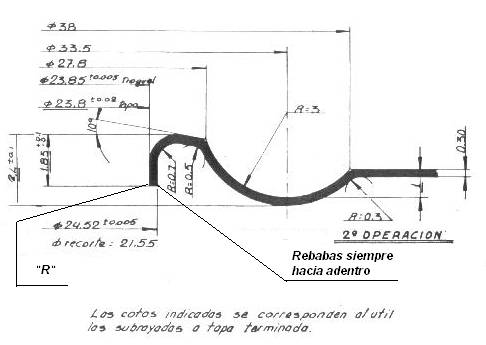
Figure nº 4: 2nd operation on “no-burr” orifice lid die for pressure neck
In order to achieve quality work, the following observations must be taken into account:
– In the cutting operation, the tooling must be in very good condition, so that a minimum burr is generated and inward.
– The radius “R” of the cutting edge must be minimum. Its ideal value is 0.06 mm with new tooling, the maximum admissible value will be 0.20 mm. It is controlled with the help of a profile projector.
– The ideal thickness of the metal is indicated in the drawing – 0.30 mm -, but it can be reduced, depending on the product to be packaged and on the conditions of mounting the neck (on loose or placed lid, temperature controlled or not, etc.) ). In each case, the appropriate value must be determined experimentally.
– The 2nd operation die must perform a vigorous ironing in the whole silhouette and reach the end of the race.
– These specifications are common for both unvarnished and varnished material.
Figure 5 reflects a rectangular lid, used for containers for brake fluid, with its main dimensions and a sectioned view of the 1st and 2nd operation.
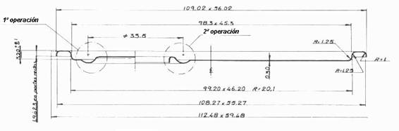
Figure nº 5: Section of a rectangular lid 99 x 46 with hole “without burrs”
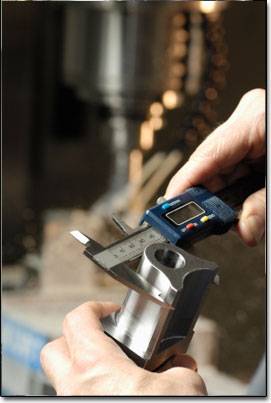
To verify the quality of the hole once finished, it is possible to prepare gauges “pass – does not pass” from the height of the skirt – height 1.85 of Figure 4 – and the diameter of the hole – height 23.8 -. To verify the latter, the verification criterion will be that the gauge “does not pass” also happens to pass, but the neck can be lifted with the gauge attached to it.
2nd.- Orifice “with burrs”:
An example of this type of hole is presented in Figure No. 6. Its execution is less demanding than the previous case, and is used for non-aggressive products, such as edible vegetable oils.
Figure 6: Pressure fitting of a neck over a hole with burrs
The manufacturing process is similar to the “burr-free” hole, that is, in two operations. The first one is incorporated into the lid die. In the drawing no. 7 a design for it for a hole also of 23.8 mm appears.
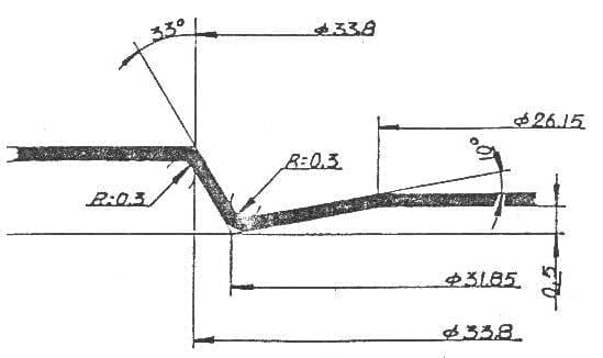
Figure no. 7: 1st operation on hole cap punch “with burr” for pressure neck
The second is carried out in an independent press equipped with a cap feeder and adequate tooling. See figure # 8:
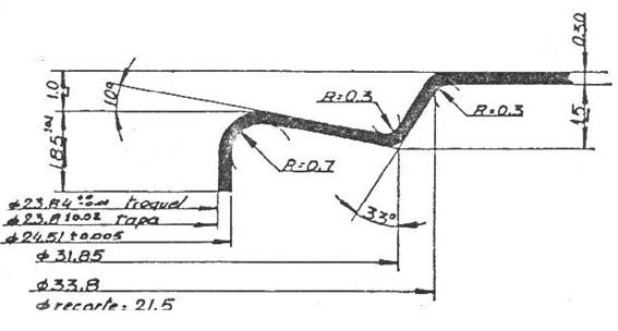
Figure No. 8: 2nd operation on hole cap punch “with burrs” for pressure neck .
Once the hole is made on the lid, whatever the type, the operation of inserting the neck is easy. A system of orientation and positioning of said neck is sufficient – for example by means of a vibration and alignment equipment for hatches and guides – and a pusher arm / head – for example pneumatic – that houses it. There are equipment in the market prepared for this work that can be assembled in the metal or the packer’s house, depending on the form of filling of the container used.
2º.- FOR ASSEMBLY BY MEETING
Another way of attaching the neck to the lid is by using a snap grip. In this option the fastening is not by pressure, but there is a union in the form of hooks interlaced between the flange the neck and the skirt of the housing. This requires a special closure equipment, which performs the operation of snap-fastening and crushing of both components. In the picture 9 a model of this type of golletes is shown.
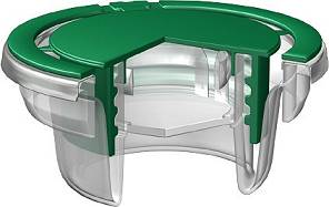
Figure nº 9: Typical neck for assembly by seaming
The shape of the neck link and the skirt of the lid have a different design than the previous type. There are many variants in the market. Also by way of example we present a couple of samples of holes for this solution. The drawing No. 10 is an alternative also performed in two operations similar to those presented above
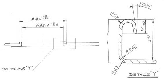
Figure nº 10: Hole for mounting the neck by seaming
For certain types of these pellets it is possible to prepare the hole of the lid in a single operation, that is, by incorporating the embodiment thereof in the lid manufacturing die, as is the option presented in figure 11.
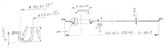
Figure nº 11: Orifice made in a single operation
In any case, this task must be carried out by the metalworker following the instructions issued by the manufacturer of golletes, which is the one with the necessary experience.
 PRODUCT DATASHEET: SAUSED PACKAGING
 PERFORATIONS FOR GOLLETES / PLUGS
 OVERHEADS AND PRESSURE PLUGS FOR METAL CONTAINERS
 INFLUENCE OF THE BOTTOM FLANGE OR THE LID ON THE DOUBLE SEAL
 DETERMINATION OF THE COURT FROM A ENDS
 DIMENSIONS FOR CUPPAGES OF ENERALED AEROSOLS
 AEROSOL CUPS
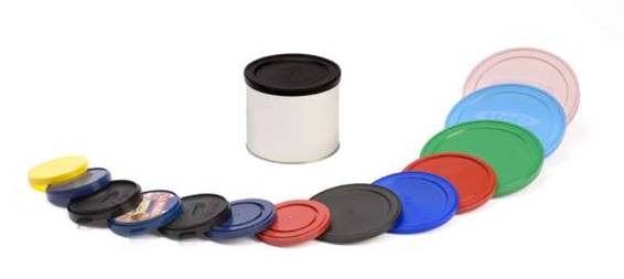
 PAINT CONTAINER CLOSURES
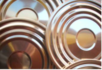
 PROFILES OF CAPS / ENDS FOR ROUND CANS


0 Comments