
SUMMARY
It is explained how to determine the fundamental measurements of a tooling, suitable for flanging a round can, in a machine with “spin” technique
INTRODUCTION
There are already several articles posted on this website on the subject of blinking, for example:
– False
We return to the tama focusing on the design of a head with a “spin” flange. The realization of the tab of the ends of a can by “spin”, is the most modern way to carry out this operation. It had its origins in response to the need to work with very thin materials and high hardness. This happened when the use of reduced double tinplate (DR) was generalized. With this development it is possible to eliminate the presence of slits on the edge of the flange, which frequently appeared with these materials if the tampon flange system was used. . From the beginning this flange mode has been designated with the English word “spin”, – turn, revolution – since the body of the can turns on itself during the operation, and at present it has given its name to this technique .
The buffers are replaced by heads that each comprise the following parts:
– A series of small rollers, inscribed in a circumference that roughly matches the inside diameter of the can body. The number of them is therefore a function of the measure of the can.
– A support, conical in shape, on which said rollers are mounted. Each roller is coupled on an axis on bearings, and turns on itself when the head is subjected to a rotation movement. These turns of the rollers can be motorized or caused by friction against the end of the can body.
– An external ring, which acts as a limiter to the external diameter of the flange, although it usually does not have to touch it, since it could cause bent or crushed edges.
The number of heads carried by each flanger is variable and depends on the speed of production you want to achieve. The set of tools includes the system of feeding and guiding the bodies (augers, stars, etc. ..), which varies with the diameter of the can.
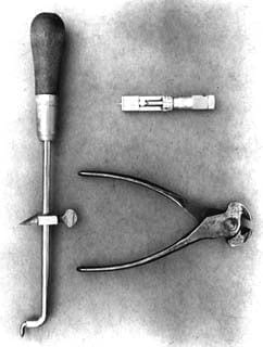
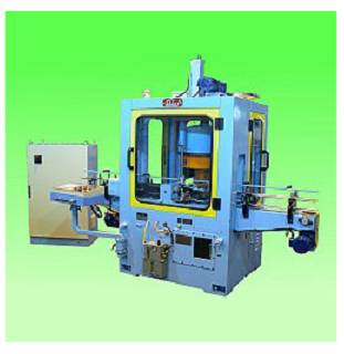
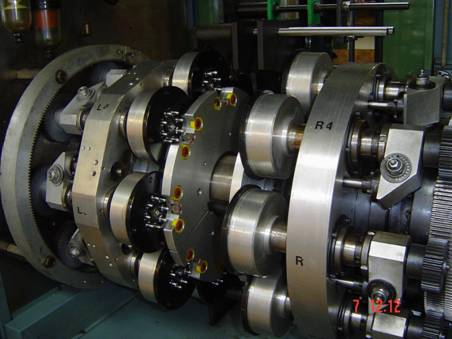
Figure 1 presents a view of a flange head of this type.
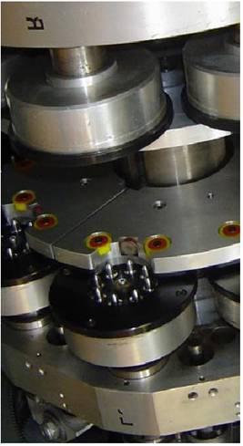
Figure nº 1: Head of flanged by “spin”
USE
Because of its way of working, this technique can only be used in round cans and allows high speeds. As we have said, its ideal application is for cans made of thin materials and high temper, Although it can be used for any material and size of can, its use is only justified for diameters less than 99 mm, since for large diameters it is not You need this way of operating and they are expensive equipment.
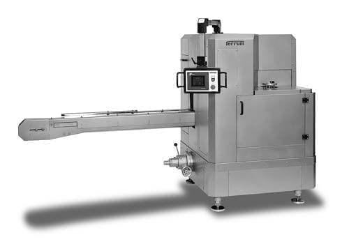
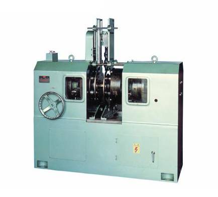
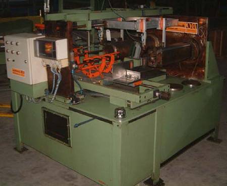
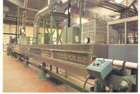
The eyelashes can be mounted modularly, within a group of machines – entalladoras, cordonadotas, cerradoras – united directly to each other, without intermediate transporters. See figure # 2:
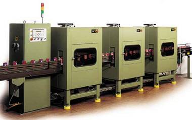
Figure nº 2: Modular group
CALCULATION
Each equipment manufacturer designs the flange heads so that they have the most common parts for different can diameters. When dimensioning a flange head, the following must be taken into account:
– In the same manufacturer the rollers are common for any format as long as it has the same flange dimension. Also the heights of the different pieces can remain the same in all cases.
– The parameters that change are:
o The profile of the roller depending on the size of the tab b
o The diameters D1 and D3 linked to the diameter of the can
o The inner diameter of the ring related to D2
Rollers:
On the rollers, there are some fixed dimensions such as their height, the angles of the conicity of the roller and the angle of the flange – see figure # 3 -. For flange length values less than 3 mm, the radius that forms it is also fixed, and of 2 mm value. The basic diameter of the roller, A usually varies between 10 to 18 millimeters, according to the manufacturer. The diameter B of the roller base is a function of A and the flange width p . The expression that links these values is:
B = A + 2p – 0.1
that is, the flange formed on the body slightly protrudes from the roller, see figure No. 3.
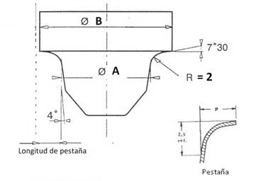
Figure nº 3: Dimensions of the roller
The number of rollers that each head carries, for reasons of available space, depends on the diameter of the can, is usually an even number and can vary between 4 to 10 units.
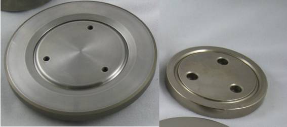
Roller heads:
The main measures of the head are those that determine the exact position of the rollers in it. That is, the diameters D1 and D3 reflected in drawing No. 4.
The D1 value is fundamental since it establishes:
a.- The adjustment between can body and head.
b.- The inner diameter of the can in the flanged area.
c.- The beginning of the tab.
The amount of said diameter D1 is related to the inner diameter, and is equal to the said diameter plus a constant that varies with the size of the can. Specifically, it is given by the expression:
D1 = d + 0.15 (for packages of nominal diameter < that 73 mm)
D1 = d + 0.25 (for cans where the condition is met: 73 < d <99)
in which :
– d = inner diameter of the can body
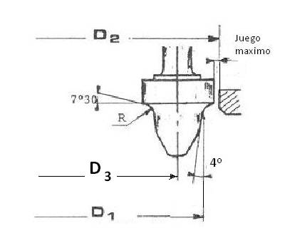
Figure nº 4: Fundamental measures of a head of flanged by “spin”
D3 is obtained by adding to D1 the value of the diameter of a roller ( A )
D3 = D1 + A
External ring:
It delimits the maximum value of the flange, although it should not come to rub against its inner diameter, but it can also touch in the area of the lateral seam, as it was said at the beginning of this article. There is always a play between the diameter of the base of the rollers ( B ) and the inner diameter of the ring ( D2 ). See figure nº 4.
The value of D2 is defined by D1 plus the tabs, to which is added a constant that determines the clearance between the edge of the flange and the rim.
D2 = D1 + 2p + 0.15
expression in which p is the length of the can flange.
FINAL COMMENTS
– The rollers and rim must be made in treated tool steel, at high hardness. Also, for the rollers, other materials are sometimes used, such as high wear resistance ceramics, or nitride coatings.
– The surface finish has to be very good, rectified and polished.
– The distance between each pair of heads should be the same in all of them, in order to maintain a can flange height and uniform eyelash lengths.
– The loss of height that occurs in a body when making its flange is similar in the case of using machines that work by “spin” or by buffer.


0 Comments