Prepared By: Carlos Herrera Alfaro; Fishing Engineer specialized in the processing of canned food at KIN e.V., Federal Republic of Germany.
Date and Place: Guayaquil, November 25, 2022
The standardization of canning plants, as well as of the equipment involved in the thermal treatment of low-acid canned foods (LACF) and acidified canned foods, must be carried out in accordance with the recommendations of 21CFR113.40 of the Food and Drug Administration (FDA), the National Food Processors Association (NFPA) and other organizations, which arduously seek the effectiveness of thermal processes to achieve microbiological lethality in the production of canned foods, the ultimate goal is to ensure that canned foods reach reliable levels of Commercial Sterility, which the FDA and the USDA define as the condition achieved in a canned food by the application of heat to produce a product free of microorganisms capable of reproducing in the food under normal conditions of storage and commercial distribution without refrigeration.
The production of canned food depends on a series of operational processes aimed at ensuring food safety and the main public health concern is the risk of botulinum toxin formation, mainly in low-acid foods. This toxin can be fatal to the consumer and is produced by Clostridium botulinum, a heat-resistant sporulated microorganism, which is used as a reference or target in thermal validation studies (HACCP), where its destruction by a thermal process programmed or established by a process authority must be reliably demonstrated.
For a time and temperature scheduled process to be efficient in its task of achieving proper commercial sterility, the processing plants and equipment used, such as pasteurizers, conventional steam autoclaves, flooded water, water spray, cascade, overpressure, etc., must be properly designed and standardized to achieve a good temperature distribution in the heat treatment to ensure that all cans processed with heat, regardless of their location in the equipment or heating medium, reach a good temperature distribution in the heat treatment, should be correctly designed and standardized, in order to achieve a good temperature distribution in the thermal treatment and thus guarantee that all the cans processed with heat, independently of their location in the equipment or heating medium, reach the calculated microbiological lethality; to achieve the latter, it should be guaranteed that there is a good supply of supplies in the plant, such as steam (lbs steam/h), compressed air (CFM), water, electric energy, etc., sufficient and of good quality.
Considerations for the Proper Equipment of Canning Plants
Canning plants that use metal containers for the production of their products mainly use conventional, discontinuous, static (AC) autoclaves, which use direct steam under pressure for their pasteurization or sterilization processes. Here the gauge pressure of the saturated steam corresponds to a temperature set according to the altitude at which the plant is located, for example, at sea level an autoclave that is heated to 120 °C (248 °F) the pressure gauge will register 14.1 PSI and at 1219 meters (4000 feet) above sea level, at the same temperature the pressure gauge of the autoclave will register 16 PSI.
Due to the length of the subject and in order to make this article more didactic, we will henceforth deal only with the standardization of canning plants that use these types of conventional autoclaves (AC).
Canning plants can now also be equipped with overpressure autoclaves to thermally process their canned goods and other soft packaging such as pouches, jars, plastic, cardboard, etc., at the same time. Usually this equipment uses atomized, cascade or flooded water and the difference with the conventional ones is that the pressures inside the equipment can be higher, for example at 120°C (248°F) they can reach 28 PSI, this condition avoids that the soft packages in the thermal treatment deform, swell excessively, burst or stretch their seals that will later damage the airtightness of the canned food, with a probable microbiological contamination of the food.
I personally recommend the use of dual autoclaves, where ETP and TFS tinplate containers are thermally processed with direct steam and soft containers with water. This option avoids premature oxidation of the cans with slight external varnishing, formation of whitish stains due to Ca and Mg salts dissolved in the water, galvanic current that detaches the external varnish and other deficiencies that are aggravated when condensates from the steam pipes and corrosive drags from the boiler are added to the process water.
In the distribution of steam pipes in canning plants, it is recommended to implement a condensate retention and return system to the boiler room; with a main manifold, traps, accumulators, retention bottles and pump that return it to the water supply tank, to reuse it by taking advantage of its remaining heat energy.
Additionally, the pipes that supply steam to the autoclaves or other equipment that require it, must be installed with the “goose neck” design, which consists of installing the supply pipes in the upper part of the main or larger pipe and then down to the equipment with a “U”, in such a way that the heaviest condensate remains in the lower part and at the end is retained in a bottle with a thermodynamic trap for its return to the boiler room.
Taking into consideration that most of the equipment and autoclaves in the canneries use steam for heat treatment, its supply must be sufficient and constant in lbs steam/hour. For this purpose, it is recommended to route a single independent pipe from the boiler room to the autoclave bench, which will be called pressurized and must maintain a gauge pressure between 100 and 120 PSI at all times. As for its sizing, it must be calculated based on its cross-sectional area in inch2, according to the number of retorts projected in the retort bank and the number of retorts that will start the programmed heat treatment simultaneously at the same time.
Plant Evaluation and On-Site Thermodynamic Balance
The plant evaluation and the thermodynamic balance in the field will allow to define if the steam generation in the boiler room in lbs of steam/hour, versus its consumption by the peripheral equipment in peak production, as well as pasteurizers and autoclaves are in balance, especially to verify if there is enough steam availability to satisfactorily complete the thermal processes that provide commercial sterility.
In this evaluation it should be taken into consideration that conventional autoclaves (AC), which use direct pressurized steam in their processes, must remove all the air from their interior before starting to count the effective time of the thermal process, since air is a much less efficient heating medium than saturated steam, this operational procedure is known as air removal, ventilation or venting and it is at this stage where the greatest steam consumption is made in the plant. It should be taken into account that in the 10 to 15 minutes that ventilation lasts in a conventional autoclave of about 6 mt (20 Feet), with a Steam Inlet of 1 ¼ inch, until it reaches 105 °C (221 °F), it can consume approximately 3500 lbs steam/h or the same as 100 BHP.
This high steam consumption also applies to other closed thermodynamic systems, such as pasteurizers, stoves, blanchers and others, which must first eliminate the air inside them in order to stabilize the temperatures of the programmed thermal process.
The plant evaluation and the in situ thermodynamic balance must be carried out in the most critical condition, that is, with the cannery working with all its production lines and at maximum capacity, in this scenario steam consumption will be higher and more representative.
For the heating of open systems such as cisterns, pools, tubs, kettles, washing machines, etc., where liquids, sauces, food or materials do not come to pressure, the steam consumption can be calculated conventionally; this is approximately 334750 BTU or 345 lbs steam/h (10 BHP) per 1 MT (2200 lbs), to bring the ambient temperature load to 100 °C (212 °F).
It is also advisable to perform an evaluation of the pipes distributed in the canning plant, considering their cross-sectional areas in inch2 and line pressures in PSI, since there may be a good production and supply of steam to the productive areas, but if the pipes are poorly sized, their flow or flow rate may be substantially restricted.
Usually when a cannery expands with new production lines, with additional equipment and with poor planning, it can be verified in the plant evaluation that there is a deficit in the steam supply to properly perform the thermal processes.
Standardization and Venting System of the Autoclave Bench
Ideally, in the design and assembly of the bank of conventional autoclaves (AC) that thermally process low-acid canned food with saturated steam under pressure in metal containers, all of them should be standardized in terms of design, size and venting system, in this scenario the temperature distribution study of one or two autoclaves can validate the rest. If this is not the case, then validation of equipment that provides commercial sterility to canned foods should be performed independently or in groups.
Considering that the elimination of air or venting from the interior of conventional autoclaves (AC) is fundamental to be able to stabilize the temperatures of the heat treatment from the beginning, we will now detail the main venting systems described by the FDA (21CFR113.40), NFPA (B 26-L) and others. These publications also mention the times and temperatures that the vents must remain open at the beginning of the thermal process, in order to obtain a good temperature distribution, but we will not mention them here because the process authority will have to define them with the validation studies.
Vents are large perforations coming out of the autoclaves with tubes, where gate or open flow valves are fitted to control air removal.
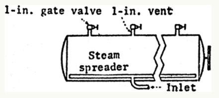
Venting of horizontal autoclaves. (A) Ventilation through multiple 1″ inch (2.5 centimeter) vents that discharge directly to the atmosphere.
This design is uncommon in canneries, as they have too many gate valves to handle. They have a 1″ inch (2.5 centimeters) vent for every 5 feet (1.52 meters) of autoclave length, equipped with a gate valve or stopcock that discharges to the atmosphere, the vents located at the ends no more than 2.5 feet (76 centimeters) from where the retort begins and ends.
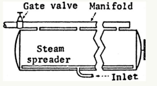
Venting of horizontal autoclaves. (B) Ventilation through multiple 1″ inch (2.5 centimeter) vents discharging through a manifold to the atmosphere.
This design is the most widely used in canning plants, as it has a large capacity and is very efficient for the initial removal of air in the thermal process. They have a 1″ inch (2.5 centimeters) vent for every 5 feet (1.52 meters) of autoclave length; and vents to
not more than 2.5 feet (76 centimeters) from the ends of the retort. Manifold manifold size: for autoclaves less than 15 feet (4.6 meters) long, 2 ½” inches (6.4 centimeters); for autoclaves 15 feet (4.6 meters) and longer, 3″ inches (7.6 centimeters).
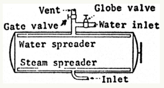
Venting of horizontal autoclaves. (C) Ventilation through the water spreader tubes used in the can cooling stage.
Vent and gate valve size: for autoclaves less than 15 feet (4.6 meters) long, 2″ inches (5.1 centimeters); for autoclaves 15 feet (4.6 meters) and longer, 2 ½” inches (6.4 centimeters).
Water spreader size: in autoclaves less than 15 feet (4.6 meters) long, 1 ½” inches (3.8 centimeters); for autoclaves 15 feet (4.6 meters) and longer, 2″ inches (5.1 centimeters). The number of holes should be such that their total cross-sectional area is approximately equal to the cross-sectional area of the vent pipe inlet.
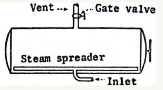
Venting of horizontal autoclaves. (D) Ventilation through a single 2 ½” inches (6.4 centimeters) top vent. Autoclaves should not exceed 15 feet (4.6 meters) in length.
They have a 2 ½” inches (6.4 centimeters) vent equipped with a 2 ½” inches (6.4 centimeters) gate valve and located 2 feet (61 centimeters) from the center of the retort.
Venting of vertical autoclaves. (E) Ventilation through a 1 ½” inch (3.8 centimeters) window.
They have a 1 ½” inch (3.8 centimeters) drain pipe equipped with a 1 ½” inch (3.8 centimeters) gate valve and with no more than 6 feet (1.8 meters) of 1 ½” inch (3.8 centimeters) pipe beyond the valve, before discharging to the environment or to a manifold.
Venting of vertical autoclaves. (F) Ventilation through a single 1″ inch (2.5 centimeters) side or top vent.
They have a 1″ inch (2.5 cm) vent in the lid or on the top side, equipped with a 1″ inch (2.5 cm) gate valve and discharge directly to the atmosphere, to a manifold or manifold.
Venting of vertical autoclaves. (G) Crateless ventilation through a vent or drain that is located at the bottom of the autoclave.
(A) VENTS
These autoclaves do not have cars or baskets, because the cans fall directly into the autoclave which is filled with water to cushion the fall, when the load is complete the water is discharged and the thermal process begins. The steam distributor is located at the top of the autoclave and ventilation is provided by the drain located at the bottom.
Clearly, other designs or ventilation systems than those described in this article can be used, but the processing plant should have tangible evidence on file, with temperature distribution studies performed by a process authority, to demonstrate that there is adequate air removal from the interior of the autoclave prior to the start of the scheduled heat treatment.
Considering that in this article we have not been able to clarify important concepts in the standardization of conventional autoclaves (CA), such as instrumentation, equipment, mandatory procedures and other topics, we will deal with them in a later chapter.
Any questions about the standardization of the autoclave bench, including design and assembly, can be addressed through Mundolatas.







0 Comments