TOOLS FOR RING LID – PAINT CONTAINERS
SUMMARY
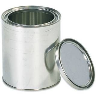
Details of the design of the necessary dies to manufacture the ring – or ring – for a double wall friction closure, of those usually used in containers to contain paint.
PREAMBLE
A specific facet in the metal packaging industry is the manufacture of containers with reusable and hermetic opening. A concrete example of this is the containers to contain paints and varnishes for the home.
In the market there are different types of snap closures, which meet this requirement of being reusable and hermetic, such as those called simple friction, double or triple. We have already discussed this issue in the article:
– Container closures to contain paints
We recommend reading it as an introduction to the one we now offer you. With this new work on the subject, we will focus exclusively on the design of the precise tools, to make a part of these closures such as rings – or also called rings – used in them.
Within the possible hoops, we have chosen the double friction type because they are the most representative and used. We will show for them, its shape, advisable dimensional design, and configuration of the necessary tools for manufacturing.
TOOLS
Obtaining these rings requires employing a process in two operations:
– A first one where the metal is cut and an approximation is made of the walls of the pressurized closure.
– A second operation where the outer area of the ring, bucket and wing is shaped, the walls are reviewed, and the mouth of the same is finished.
These two operations, although a transfer type press can be made, the normal ones are to execute them on two classic gooseneck presses, joined together by a gravity lifting and dropping system, which transports the pieces from the first to the second operation.
The first press is fed from strips of material cut to the appropriate size, stacked in a feeder, while the second press must have incorporated a parts feeder. The latter is usually an introducer arm with pneumatic drive.
FIRST OPERATION
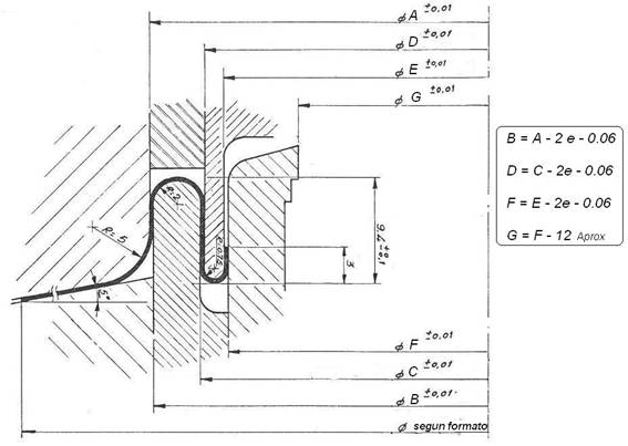
The sketch obtained in the first operation has an approximate “U” shape inverted with its long edges. In drawing # 1 you can see the profile of the same, as well as the different parts of the die that shape it.
Figure No. 1: Section of the 1st operation of a DF ring
The cutting diameter of the disc, necessary to form a ring of this type, is approximately 11.5 mm greater than that suitable for the bottom used in the container. That is, there is a difference of about 11.5 mm between the cut of a ring type “double friction” and a flat bottom of the same format. This data is a valid reference for medium packaging sizes, between ½ and 1 liter capacity. For smaller or larger formats this deference changes proportionally. It also influences the dimensions of the wing and type of closure chosen. The indicated data corresponds to a type I or II closure.
At the mouth of the “U”, where the closure plug is friction-fitted, it is given a width of 6 mm for containers of the aforementioned size – ½ to 1 liter of volume – that is, the difference between level B and C of the drawing is 12 mm.
The space reserved on the panel of the ring, for the formation of the housing tray of the mandrel of the closure, is approximately equal to the mouth of the friction “U”. Therefore, an approximate formula to define the diameter A (see drawing no. 1) is the following:
Diameter A = Diameter format (X) – 11 mm.
Once the value of A has been determined, for the rest of the diameters that determine the ring, the formulas shown in drawing no. 1 can be applied.
It is necessary to eliminate a central disc, for making the mouth of the ring. The cut of this disc is defined by the diameter G
As for the heights, in this drawing reference data are always given referring to containers of capacity between ½ and 1 liter, as already said. The radii of curvature of the metal are defined by the values of the different diameters of friction, see figure No. 1, except the outer one, whose appropriate value is 5 mm.
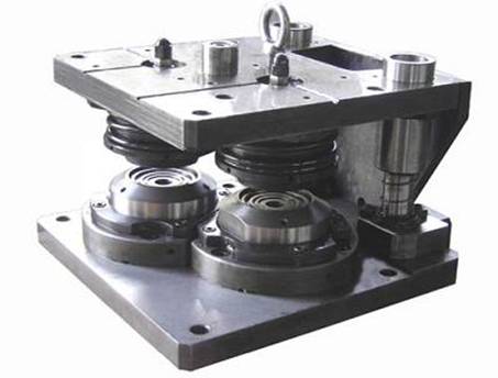
With the design of the first operation of the hoop determined, we can focus on the project of the press tool necessary for its conformation. Figure 2 presents an example of a die for that matter.
This tool performs the following sequential actions:
– Cut metal disc from the fed strip
– Trims central disc for shaping the mouth of the ring and eliminates it
– Inlay the friction walls of said hoop
Figure nº 2: Die for first operation of double friction rings
Therefore in the die two circular and concentric cuts are produced. The two pairs of knife and punch must be perfectly aligned. The elimination of the central cut is made through a lower tube, housed in the center of the pressure system.
Said cut is pushed inside the tube by the action of ejectors loaded with springs, see figure No. 2.
For the rest, it is quite similar to a die of funds, with the particularity of having a pair of punch and matrix centers, designed to generate the double friction wall.
When dimensioning the parts of the tool, it must be borne in mind that there is always a slight elastic deformation of the ring, in relation to the measurements of the tool. This occurs mainly in the diameters of the friction walls. Since the adjustment between the ring and the stopper must be very precise to maintain an effective hermeticity, this recovery of the material must be taken into account, so that the measurements of the tool will not coincide with those that are desired to be obtained on the piece. In the work that was referred to at the beginning:
– Container closures to contain paints
a table is included where the measurements of the piece to be obtained are compared with their corresponding ones on the tooling.
SECOND OPERATION
The piece obtained in the first operation is transferred to the second press by the appropriate means, such as a magnetic lift and a fall by gravity. At the exit of the first press you have to turn the piece, so that it enters the second with the mouth of the “U” of friction upwards.
As we have already said, this second press must be equipped with a parts feeder. The same will be introduced one by one on the tool mounted in the aforementioned press. It is not the intention of this work to enter into the detail of these mechanisms. We will develop them in another place.
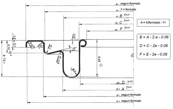
The second operation ends the hoop, transforming the sketch made in the first phase. In figure 3 the ring resulting from this second operation is presented. The tasks of the same are the following:
– Form the wing and bucket necessary to make the closure of the ring on the container. The wing in this case will be equal to the normal bottom of the same diameter, used at the other end of the boat. The base of the bucket must have an inclination in elevation, see figure no. 3, so it is avoided to re-sink it with the effort of introducing the plug in the hoop.
– Recalibrate the walls of the “U”, to reaffirm its appropriate measures.
– Curl the edge of the rim’s mouth to eliminate sharp edges, which would produce cuts of hair from the brush and what is worse, the easy contact of the steel seen from the rim with the paint, which in certain types of them can have a general presence of rust .
On drawing no. 3 the different diameters have been marked using the same letters as in drawing no. 1, although some new ones appear, such as:
– X: Value of the diameter of the cuvette and adjustment of the closing mandrel, designated as “format”. The relationship between this starting value and the diameter of wall A is indicated.
Figure No. 3: Section of the 2nd operation of a DF ring
On the drawing appear the formulas for the determination of each diameter. The heights appropriate to this example are also indicated, which are related to those applied to the first operation.
Once the hoop profile is defined, we will proceed to design your corresponding tool. The same has to perform the tasks indicated above.
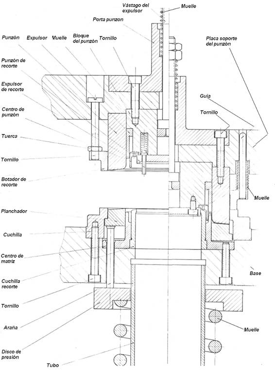
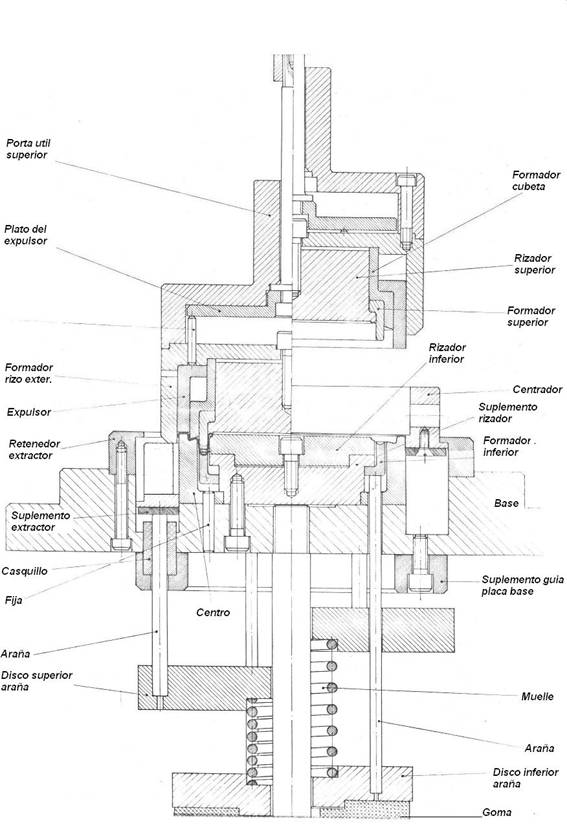
Its shape is reflected in figure No. 4. It is a forming die, without any cutting function. This simplifies its construction somewhat. The 1st operation of the ring arrives at its position on the lower part of the die through a recess, or access channel, practiced in the “Centering”, which has a lateral width slightly greater than the outer diameter of the 1st operation. The base of this slot will be flush with the level of arrival from the feeder of said 1st operation. This “Centering” is the piece that stands out from the bottom of the tool and has two functions:
– Facilitate the arrival of the piece
– Align it on the “Center”
The lower pressure system is equipped with double spider, to facilitate the exit of the matrix from the finished ring. It rises with the upper part of the die and is ejected by means of the “Ejector” when it reaches the end of the press race.
A study of drawing no. 4 will show the complete functioning of the tool. This is represented on the left side in closed position (bottom dead center of the stroke) and open on the right side (top dead center)
Figure nº 4: Die for second operation of double friction rings
Both the 1st and 2nd operation die will work better if they are guided by columns. In the first case due to its double cut is almost imperative.
METAL
The tinplate or TFS used in the manufacture of rings should be of low temper and a thick gauge, in order to eliminate risks of cracks, breaks and exaggerated deformations due to internal stresses of this material. For rings of containers to contain ½ to 1 liter of product, suitable values would be: Temple T2, caliber from 0.26 to 0.29 mm. Its coating will depend on the aggressiveness of the product to be contained.





0 Comments