SUMMARY
Dimensioning, tooling for its execution, and quality control for the necessary drilling to be made for the assembly of a metal neck.
INTRODUCTION
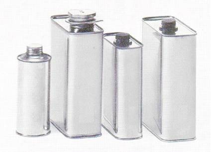
In packages intended to contain industrial products, it is common to provide them with a neck or spout that facilitates their emptying. This is especially useful when the product contained is a liquid such as a solvent, a varnish …
This neck is covered with a cap that also serves as a guarantee seal, to ensure its inviolability before use. The types of golletes and taponen used by the market are very varied. There are metallic, plastic, mixed, etc. But in all cases always have to make a hole in the lid of the container to accommodate this neck and fix it.
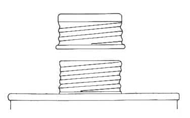
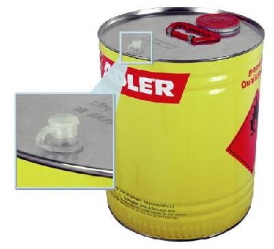
If the neck / plug is made of plastic, the attachment to the hole is usually by pressure adjustment. On the other hand, if this neck is metallic – tin – for its fixation, welding is used. An example of a container with a neck / metal cap is presented in drawing no. 1:
Figure nº 1: End of the container with metallic neck
ALLOY WELDING
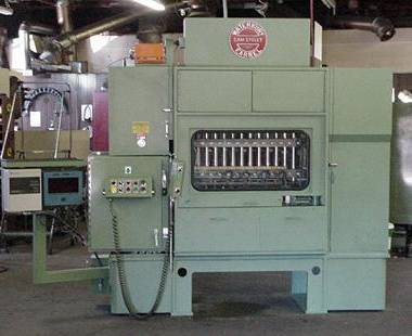
This welding can be done electrically by points, or what is more common by means of a contribution of a tin-lead alloy in the area of fixation of the neck on the perforation made on the lid of the container. This last alloy is applied cast by means of an equipment that consists of an injector nozzle that deposits a jet of liquid alloy on an outer point of the lid-neck connection zone. This nozzle is opened or closed by the action of an inner needle charged with a spring and which is activated by means of an electromagnet or by a pneumatic system. The nozzle acts when the presence of container with neck is detected by means of a sensor head.
The equipment is completed with an alloy tank located in a plane superior to the one of application and that is heated by resistances. The alloy flows by gravity through a conduit that communicates with the nozzle. This conduit must be kept warm by electrical resistances and thermally insulated so that the alloy remains liquid. When the activity ends, you have to purge the circuit to keep it free.
In order for the welding to run and seal the entire area, it is necessary to previously apply a paint strip to the area. This is also done by means of a pre-nozzle to which the paint stripper comes from a reservoir and is applied intermittently by a system similar to that used with the alloy. The whole set is installed on a conveyor through which the containers run.
The containers are then passed under a gas burner battery that refuses the alloy by applying heat to the welding zone. By capillarity, molten tin extends throughout the neck-piercing area, covering the cutting edge of the hole where there is exposed steel and that may present pockets of oxidation.
DRILLING
To prepare the hole on the lid that will subsequently lodge the neck, you can resort to:
– 1º: Incorporate on the die of manufacture of the cover pieces that perforate and conform the same.
– 2nd: Make this operation after the manufacture of the lid, starting from normal funds, performing the same with a special tool mounted on a press equipped with a feeder of funds.
The first option is more economical to avoid a second operation, but the second is more flexible since the same tool can be used for different sizes of lids.
We will describe an example of tooling to make this hole valid for the second case.
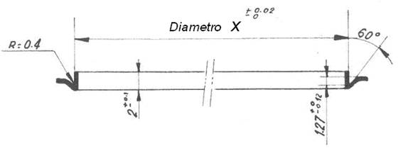
The perforation to accommodate a metal neck welded by tin-lead alloy to the cap usually has the shape shown in figure 2 nd. It consists of a hole with an outer skirt facing outwards. The possible cutting burr is positioned on the inside edge of this skirt.
Figure nº 2: Perforation for metallic neck
The outer diameter of the housing X should be 0.40 mm smaller than the inside diameter of the neck at its base. Said neck holds it in the outer groove of radio 0.4 of the perforation
TOOLS
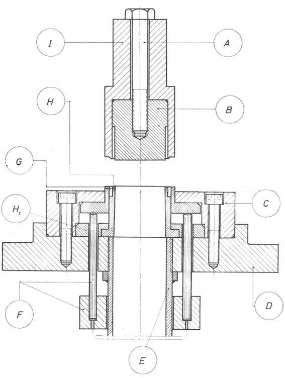
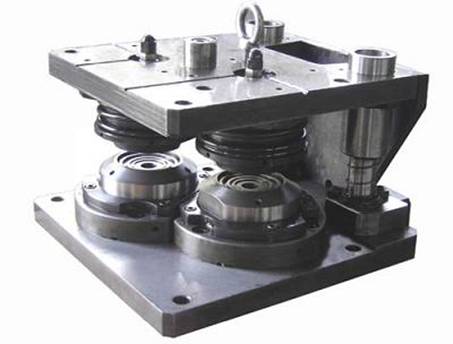
The punch to make the perforation is very simple. Figure 3 shows an example. It is formed, in its upper part of a cutting punch A, with its punch holder I, joined by means of the screw A. The cutting diameter of the punch, for a perforation of the type reflected in the drawing No. 2, is approximately 4 mm . smaller than the diameter X of it. The inner diameter of the punch holder matches the X value.
Figure nº 3: Drilling for metallic neck
The lower part is composed of a blade H with its fixing ring H1, a dropper ring G, a part C for fastening the assembly to the base D and a lower pressure system.
The value of the outer diameter of the blade H, which calibrates the metal inside the hole, must be equal to X minus two times the metal thickness of the cover. The inner diameter of the dropper ring G is X plus 5 mm. The rest of the measures are defined in a manner proportionate to those indicated.
As for the material to be used for the construction of the different pieces will be tool steel – non-deformable – with high chromium content. All those in contact with the tinplate should be treated to a hardness of the order 60-62 HRc, except the punch that will be a little softer. The rest can be of a more economic steel.
QA
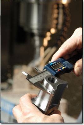
The perforation must be controlled frequently with the appropriate means. To do this, a control plan will be established by sampling and two gauges will be used to verify their diameter and heights.
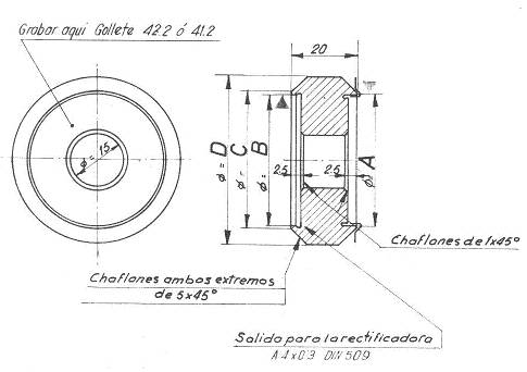
Figure 4 shows a simple “pass-not-pass” gauge that is very valid for checking the outer diameter X of the bore.
Figure No. 4: Gauge for drilling diameter control
To dimension it in relation to the X value to be verified, the values shown in the following table can be used:
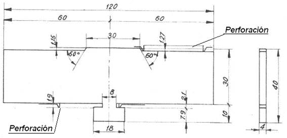
For the control of the height of the skirt of the perforation and its slope in relation to the panel of the cover, a gauge can be used as indicated in drawing no. 5
Figure No. 5: Drill height control gauge
COMMENTARY
For holes intended to accommodate plastic nozzles / pouring shells, with the corresponding modifications, tools similar to those described can be used.
On plastic necklaces there are other works on this Web.








0 Comments