
 INTRODUCTION
The most classic geometric shape of a can is the cylindrical, also being the easiest to make. But it is very common that certain products are commercially associated with other different presentations such as rectangular, oval, trapezoidal, etc. You can also demand cans with a circular bottom and cover but with different designs, such as truncoconical, hexagonal, cubic, etc. In these last forms, logically the non-cylindrical configuration of the body, does not affect its ends, which continue to maintain their cylindrical configuration to be able to couple the lid and the bottom. An example of this type of packaging is shown in Figure 1
INTRODUCTION
The most classic geometric shape of a can is the cylindrical, also being the easiest to make. But it is very common that certain products are commercially associated with other different presentations such as rectangular, oval, trapezoidal, etc. You can also demand cans with a circular bottom and cover but with different designs, such as truncoconical, hexagonal, cubic, etc. In these last forms, logically the non-cylindrical configuration of the body, does not affect its ends, which continue to maintain their cylindrical configuration to be able to couple the lid and the bottom. An example of this type of packaging is shown in Figure 1
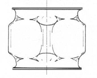
Figure nº 1: Can with cylindrical ends and cubic central body, obtained by expansion.
For the can manufacturer, before the demand of a can of non-cylindrical configuration, it is proposed to take the decision of which is the ideal procedure to shape the can body. Like all things, since the first rectangular cans were produced (which are the most frequent) up to the present times, the primitive solutions have been evolving, until achieving results of better quality and higher production speed. Today there is a wide range of equipment manufactured by different firms in the market that allow you to choose between several options. CONFORMING PROCEDURES We will comment on the most common ones, thinking that we want to manufacture a rectangular can. 1st method The oldest procedure is to use a folding machine, automatic or manual, and with it, starting from the flat development of the can, make the four sides of it if it is rectangular or square, curving the four corners with the desired radius. It is also possible to fold the four corners in a non-parallel manner, to prefigure, for example, a pyramid trunk, or another desired shape. To work with a small conventional folder, it must be prepared properly, sizing with the convenient radius of the folding roller, place a long feeding table to deposit the flat bodies (if it does not have the machine of it), put a few stops of low height on this table that delimit the position of the body in the situation of folding of each corner, etc. At the ends of the body a small margin must be left for the joining overlap. It is performed, usually in the vicinity of a corner or in it, by means of a manual welder. In the past, this operation was carried out in a manual engraver and joined with a tin soldering iron. In image no. 2 a manual folder and welder are valid for this way of working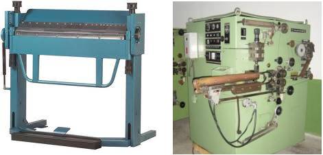
Figure nº 2: Minimum basic equipment to manufacture a rectangular body
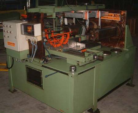
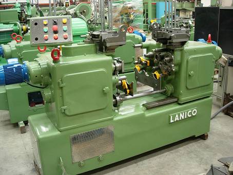
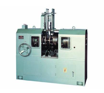
. This procedure is very slow and little used at present, although for small productions it is the cheapest installation. Suitable second-hand equipment can be found in the market. 2nd: method: It is the most used currently. It consists in manufacturing a cylindrical body, with the same development and height as the body of the can so that it is desired to obtain. For this a conventional electric welding machine is used, any of the many on the market, although the loss of overlap in the weld will be as low as possible, to facilitate the subsequent expansion, a very thick welded seam will present an excessive resistance to the deformation. Actually the development of the cylinder must be somewhat less than the theoretical of the rectangular can to be obtained, since in the subsequent expansion there is a slight stretching of the material. To know how the development and height of the body of a non-cylindrical can manufactured by this system is calculated, the work can be seen: Determinación de medidas de un envase rectangular o no cilíndrico Then proceed to transform the cylindrical body into rectangular – or other chosen form – by means of a specific machine called expander. There are different types on the market, made by different manufacturers, which can vary a lot in their design. Initially these machines can be classified into two groups: 1º.- Those that make the transformation of the body shape in a progressive way, going from the cylindrical configuration to the desired one by means of intermediate appearances in a continuous way, that is, in a single process. 2º.- Those who execute this transformation quickly. 1º.- Progressive expander: It is positioned immediately behind the welding machine. The union between both is done by a small magnetic conveyor, which ensures the immobility of the body of the can, so that the welding line does not turn or change position. The machine itself is a kind of passage, consisting of: – An interior last that progressively changes its section from round to rectangular shape, and on which the can slides. – A series of external driving rollers, which act on the body, deforming it on the last. An interior view of this type of expansionadota appears in photo # 3.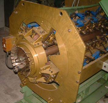
Figure nº 3: Detail of a progressive expander
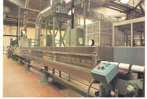
When it is necessary to protect the inside of the side seam with varnish, it is necessary to pass the application pipes through this machine from the welding machine, putting on this varnish and curing it after expanding the body. Photo No. 4 presents an overview of a similar machine.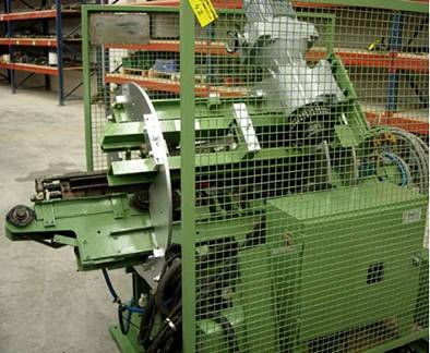
Figure nº 4: General view of a progressive expander
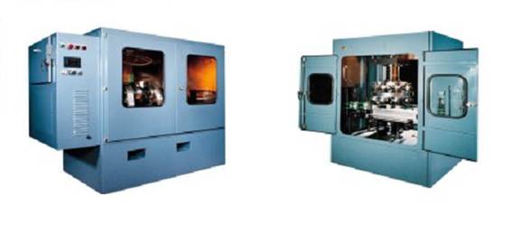
2º.- Fast or instantaneous expander: – A system for feeding cylindrical bodies. – A head of orientation of the welding in its concrete position – An expanding head. – A discharge of reformed bodies The machine can be mounted at a point farther from the welder than the previous type. It even allows the welding to be previously protected with varnish, provided that the can reaches the expander sufficiently cold. As the working rate of this type of machines is low, when a certain speed of production is needed, and the format of the can to be manufactured is not very large, double machines are used, that is to say equipped with two sets of twin heads, which they work in parallel. – Body feeding system: If the cans enter horizontally in the machine, they are usually simple drops of gravity, which collect the bodies of an aerial conveyor by cable. When it comes to double machines, they need two ways of feeding and unloading bodies, so a splitter is required at the entrance and a regrouping at the exit. An example of this case can be seen in photo nº 5: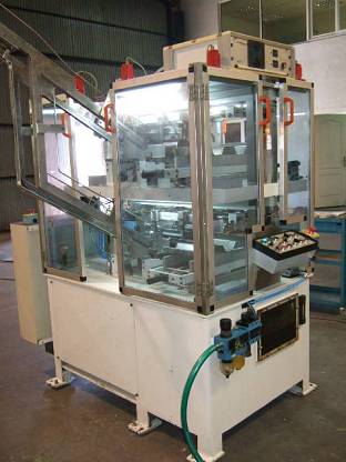
Figure nº 5: Automatic double expander.
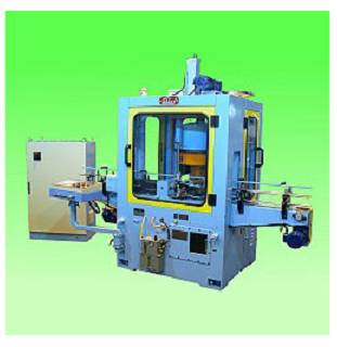
– Welding orientation head: In cans of non-round shape, for example rectangular, it is necessary to position the electric welding of the side seam always in the same place, so that it is invariably present in relation to the four faces, more precisely if they are lithographed. In this case the welding arrives at the machine in a random placement, due to the movement of the body along its running between the welder and the expander. To ensure the position of the same, a horizontal cylindrical head is used, which quickly turns the body and stops it when the union reaches the right place. The detection of the position of the seam is made by means of an external precision sensor, which can be by photocell, mechanical, etc. whose selection depends on the type of welding. To the left of photo no. 6 you see a welding orientation head. The body is inserted in the head of orientation from a cradle, which collects the same coming from the feeding system, driven by a pusher arm. Once the body is oriented, it is deposited on the same cradle from where it has been introduced to the head, and from there, by an alternative movement thereof, it moves in front of the next head. So that the body does not move, it is immobilized by means of a soft magnetic field.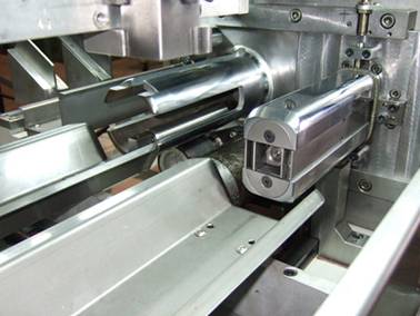
Figure nº 6: Orientation and expansion heads
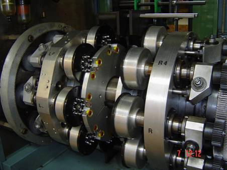
– Expansion head: It receives the oriented cylindrical body, pushed from the cradle, and deforms it to the desired silhouette. For the new form of the can to be permanently maintained, the metal must be subjected to an effort that exceeds its elastic limit. This head, which has a section close to which the body has to take, consists of a fixed part, and another that moves expanding when the body has been introduced. When the moving part reaches its maximum stroke, the development of the head section coincides with the perimeter of the final shape of the body. In the case of photo no. 6, where you can see the expansion head in first term, it is a tool for rectangular packaging. The lower part of this tooling remains fixed, while the upper part rises when the body has been introduced, that is the smaller side of the rectangle with rounded corners coincides with the dimension of the smaller side of the expanded body, while the larger side in the retracted position of the tooling is lower than the larger side of the body. This allows the introduction without difficulty of the body in its initial cylindrical position. Then the upper part – or shell – ascends by going through a route until the larger side of the tooling reaches the desired value for the can. The movement of the shell is made by the action of a horizontal expander stem, which moves alternately on the axis of the tooling, equipped with inclined planes, acting on other – expansion wedges – arranged inside the shell, the Return to the starting point is done by the action of springs. Depending on the shape that you want to give the can, the design of this tooling can be several, but generally using the principle described above, for example in drawing no. 7 a section of an expansion head for a square canister is presented. In this case, it has four mobile shells, coinciding with the four corners, which are pushed open by the expansion wedges, on which the central expander stem acts. Four fixed shells are positioned in the center of the four faces, which initially center the body when it is fed in a cylindrical shape.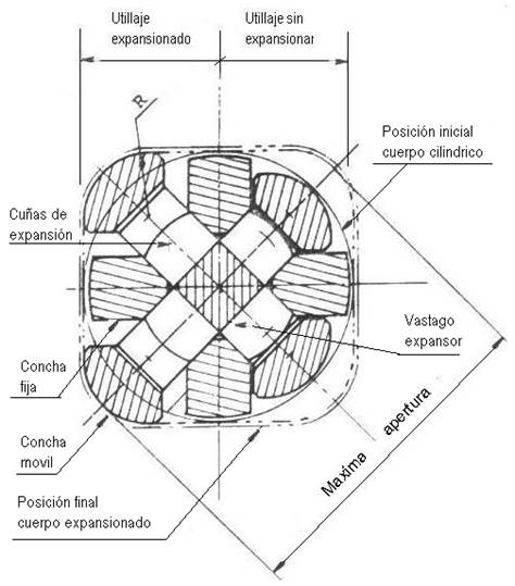
Figure No. 7: Section of an expansion head
– Download: Transformed the body to its new shape, it is removed from the head by means of an extractor arm that deposits it in the unloading cradle. This is transferred by transport system to the next machine. When the expansionadota is double, the production of both parts must be brought together in one way. This type of rapid expanders can also work with the can body in an upright position. In this option the expansion head works suspended, and the can is inserted in it from below, by means of a plate with ascending-descending movement. There are machines that have a third head, whose mission is to soften the faces of the body once it has been expanded, that is to say to mark on these faces nerves or facets of reinforcement. With this, several effects are achieved: – In the expansion operation, when the metal surpasses its elastic limit, irregularities or irregular deformations often appear on the long sides of the body, which give the can a bad appearance. With these nerves these deformations are eliminated. – Said ribs, which are normally positioned in the direction of height and only on the larger faces, give more resistance to the body of the can. This third head is not required in small packages. It works by a combined system of stamping from outside to inside on each side. The technology for the manufacture of non-cylindrical cans, also has application to produce frustoconical cans, widely used as cans for painting and other industrial uses. These cans use different types of closures and the most common are the so-called “pail” types. Expansion techniques require the use of metals of thickness somewhat higher than their equivalent in cylindrical and lower hardness. square-shaped aluminium cans
 RELATIONSHIP OF HEIGHTS IN MANUFACTURE OF AEROSOL CANS
 TAPAS TWIST-OFF.- FORMATION OF CURL AND NAILS
 MANUAL DEPALLETIZER OF PACKAGING
 SEAMERS MACHINES
 CALCULATION OF THE TABS OF MADE A FLANGE
 NECKING BY ROLLER
 MEASUREMENTS OF A SPING FLANGING
 LINE FOR BEVERAGE CANS “THREE PIECES”
 TANNING


0 Comments