INTRODUCTION
La soldadura eléctrica, de la costura lateral The electrical welding, of the lateral seam of the bodies of the metal containers, is together with the seam of covers and bottoms, the critical point where a boat can present leaks in the manufacturing phase. Therefore, it is necessary to maintain a quality verification system for said welding. The electrical welding, of the lateral seam of the bodies of the metal containers, is together with the seam of covers and bottoms, the critical point where a boat can present leaks in the manufacturing phase. Therefore, it is necessary to maintain a quality verification system for said welding.
Increasingly, welding machines are better equipped with effective means of automatic quality control of each point of the electric welding, and better joint standards are achieved. However, it is good to have some simple means that can verify the mechanical resistance that the welding admits. A periodic control will ensure the absence of systematic failures.
There are several possibilities to perform this control, using simple and inexpensive equipment, including possible manufacturing in the workshop itself. Among others we will comment on the following tests:
– Welding flip
– Welding deformation
– Tear of the weld
VOLTEO
This test consists of turning the welded body upside down, that is, leaving the internal part of the weld outside. It is also called “sock” test, because the can is turned over as if it were a sock. The bending radius used for the turning is small, of the order of 1.5 mm, and therefore the welding points are subjected to an important bending stress. If any of them is defective, the welding is detached by said point.
The equipment necessary for this is very simple. It consists of:
– A fixed plate where the opposite end to the overturning of the body rests. To fix it, a groove is made in the working face of said plate, in the form of a circumference of diameter equal to the body of the container.
– A mobile head, where the end of the body is inserted where its turning begins. The entrance guide wall has a slight inclination to facilitate its introduction, ie in the form of a truncated cone. The diameter of its base coincides with that of the interior of the body and ends in an arc of small radius, as we have said, of approximately 1.5 mm. See drawing nº 1
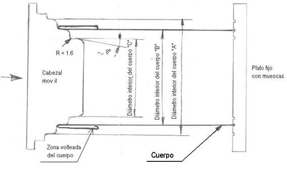
Figure nº 1: Schematic drawing of the active part of a body turning equipment
For the test, one end of the body is resting on the fixed plate and the other is inserted lightly into the moving head. The thrust of the latter, as it advances, will make the metal of the body flow outward, forming a new wall parallel to the primitive, and separated from it a distance equal to the radius of the mobile head. See figure nº 1.
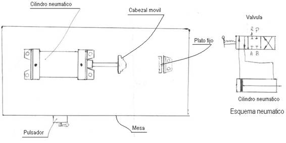
The moving head is moved by a double-acting pneumatic cylinder, operated by an appropriate key with pushbutton. See drawing nº 2.
Figure nº 2: General sketch of turning equipment
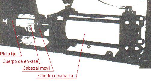
The pneumatic cylinder used must be robust, so that it commands sufficient force for operation, at least 50 mm in diameter and a stroke less than half the height of the body. See figure 3
Figure nº 3: Body turning equipment
The set can be mounted horizontally, on a small table, or vertically. In this last case the fixed plate will be down, acting as a support table.
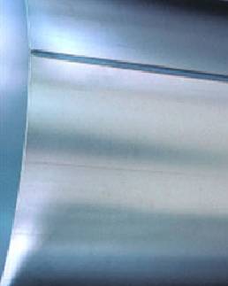
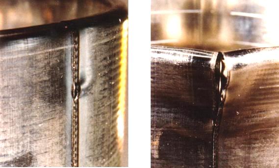
Turned bodies sometimes have slight undulations parallel to their base. The weakest points of the weld are at the ends, so to check both, you can do the double test, that is, turn one end in a small section and then invert and turn the other. Photo No. 4 shows two bodies turned over with welding failure.
Figure No. 4: Turned bodies with weld failure
The advisable way to carry out this test is:
– Take 10 consecutive bodies at the exit of the welder and number them.
– Proceed to flip the first 5 supporting the start of the welding on the fixed plate.
– Repeat the operation with the remaining 5 in opposite position, that is to say with the end of the welding on the fixed plate.
– Analyze the results
DEFORMATION
It is an alternative to the previous test, which also uses a pneumatic drive tool. It allows to incise, from inside to outside, on the seam along its entire length, deforming this area permanently. If the rupture of the wall of the body is produced, it should not be due to the welding, since this, if done well, resists more than the rest of the tube.
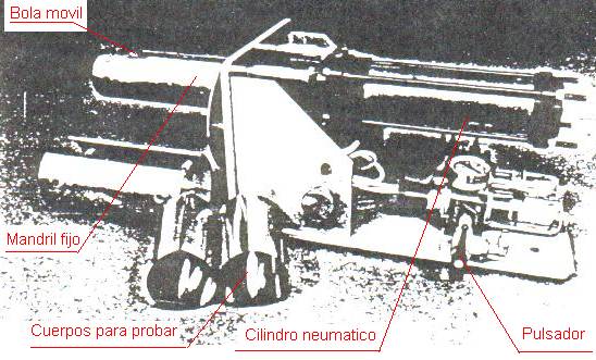
The necessary equipment, as shown in figure 5, consists of a base on which the set of pieces is mounted horizontally. The driving element is a double-acting pneumatic cylinder, operated by a safety button. Said cylinder is fixed, on the side of the end of the rod, on a vertical wall. On the opposite side of the wall sits a cylindrical mandrel, of a slightly smaller diameter than that of the can. The rod of the cylinder moves inside the mandrel, bearing at its end a ball, which emerges above the upper generatrix of the mandrel, and moves along a groove made therein. See figure nº 5.
Figure nº 5: Welding deformation tool
The procedure is as follows:
– Take 5 consecutive bodies and number them
– Insert each of them in the fixed mandrel. The welding must be positioned on the groove of the mandrel, and its end in contact with the ball.
– Operate the pneumatic cylinder. The ball will move along the mandrel pushing the weld out and deforming this area
– Remove the tube and examine the weld strip.
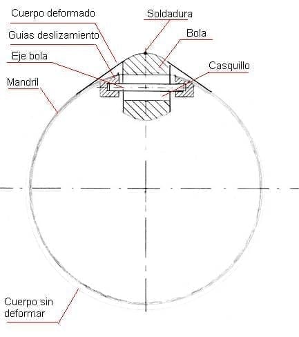
Figure 6 shows in sketch a section of the mandrel, with the assembly of the ball. The undeformed body fits comfortably into the mandrel. When the ball penetrates the body, the development of the geometric shape, determined by the envelope of the ball plus the mandrel, is superior to the development of the body of the can, causing a permanent deformation in the area of the seam.
Figure No. 6: Deformation tool section
There should be no weld points detached. When the height of the body is larger than the stroke of the pneumatic cylinder, repeat the operation in each one by turning it 180º, this will deform the area of the seam not tested.
SCRAP
Another way to verify the quality of the weld seam is by detaching it from the body. Thus it is possible to test if the resistance is uniform in all its points.
Required equipment:
No special tools are required, only the following material:
– Scissors to cut metal, to make some incisions on the body
– Pliers to tear the welding area
– Cylindrical mandrel. A simple steel cylinder supported horizontally at one end, mounted on a work bench. Its outer diameter will be somewhat smaller than that of the can. It is used as a support for the body of the boat during the tearing of the seam.
Verification method:
– Take 6 consecutive tubes from the welder and number them.
– On the front of the welding of three tubes and on the back of the other three proceed as follows:
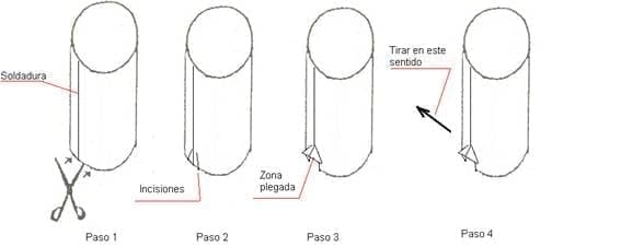
- Make, with the help of the metal cutting scissors, two triangle-shaped incisions on each side of the end of the weld. See figure No. 7, steps 1 and 2
- Fold the area of the incision, elevating it towards the outside. Step 3 of figure no. 7. Insert the body on the support mandrel, with the part folded inwards and upwards.
- Aided by pliers, pull the cut area in the direction of the seam, respecting an angle of traction of around 60º to 80º. Step 4. The weld must be completely detached, that is, along the entire height of the body. If only one section is torn, it indicates that it is not correct.
- Do a test of the torn weld and fold it repeatedly at several points and check the breaking strength. It must withstand successive bends without breaking.
Figure No. 7: Steps for the welding tear operation
There are other types of tools on the market, which are designed to perform the same task, but with the ones indicated here it can be done perfectly.
The “flip” and “deformation” are comparable tests, so it is sufficient to have one of them, in addition to the “tear”.



0 Comments