
Considering this as of interest, the way to calculate the geometry of the zigzag cutting profile of sheets and tin strips intended for the manufacture of funds is developed in this work.
INTRODUCTION
The need to reduce costs, has gradually been implementing, in the second half of the last century, the imperative to make the most of the surface of the metal dedicated to the manufacture of caps and funds. For this, the zig-zag cut was first introduced in the press bands, and subsequently, the same technique in the cutting of sheets from coils.
In this work we intend to expose the basic notions for the calculation of the silhouette, or profile, of these zig-zag cuts. In the Spanish language, to designate this type of shearing, the use of the English word “scroll” has been generalized. Therefore, we will use this term from now on. We will call the primary scroll cut, the one made in the chopping lines of coils, and the secondary scroll cut to the fact about shears for the preparation of strips or bands for presses.
Although strips are sometimes used for simple dies – of a single punch – and therefore only contain a row of funds, the most usual case is that which is intended for double dies, that is to say double-row bands. Therefore this study will focus on this last type.
INITIAL PARAMETERS
To start the calculation, we have to know some data beforehand. These are:
– D = The cutting diameter of the material needed to cut the lid. You must have previously calculated and verified practically the same.
– N1 = Number of cuts to be obtained per band. We will be limited by:
– the maximum / minimum cutting step of the coil cutting line.
– the maximum / minimum blade width admitted by the shear scroll.
– the maximum / minimum strip length allowed by the press.
These data will be indicated in the manuals of the machines .
– N2 = Number of bands we want to get per sheet. It will be limited by:
– the maximum width / bobbin width that the cutting line admits.
– the maximum / minimum blade length that the scroll shear supports.
– F1 = Minimum cut between cuts.
– F2 = Cut between cut and side edge of the band
– F3 = Cut between cut and end of the band
– F4 = Cut between edge and edge of battlement
The value of these cuts is linked to the precision of work of the press and the quality of the die.
In figure 1 these initial parameters are indicated, for better identification they are framed in rectangles.
Let’s take an example to better follow the calculation,
Assume the following values for a certain cover:
D = 92 mm.
N1 = 18 (2 rows of 9)
N2 = 5
F1 = 1.1 mm between contiguous cuts
F2 = 1.8 mm between cut and side band edge
F3 = 0.8 mm between cut and band end
F4 = 2.25 mm between cut and crenellated edge
See figure # 1 below. In it we have represented by letters the different dimensions that define the different parameters of the cutting scheme.
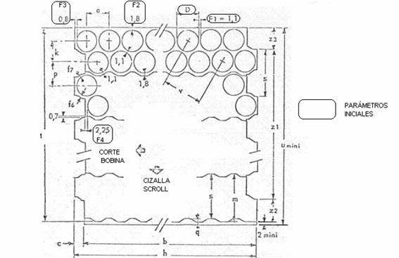
We have also marked with two arrows, the directions of advance of the material in the operations of cut of coil, and cut in shear scroll. We will now develop the calculation of the different dimensions.
1º.- Distance between two cuts: a = D + F1 (a = 92 + 1.1 = 93.1)
This value a corresponds to the advance step in the press.
2º.- Coil cutting length: b = ax (N1 / 2 – 1) + D + 2F1
( b = 93.1 x 18/2 – 1) + 92 + 2 x 0.8 = 838.4 )
It is the step of advance in the line of cut of coils
3º.- Depth of battlement in primary scroll: c = a / 2 – F3 + F4
( c = 93.1/2 – 0.8 + 2.25 = 48 )
4º.- Leaf length: h = b + c (h = 838.4 + 48 = 886.4)
5º.- Distance between center lines of the same band:
k = a/2 x 1/ tg30º
k = 93.1 /2 x 1/ 0.57733 = 80.624
6º.- Bandwidth: m = 2F2 + D + k (m = 2 x 1.8 + 92 + 80.624 = 176.224)
7º.-Distance between contiguous rows of two bands:
p = V (2F1 + D)(2F1 +D) – (F1/2 + D/2) (F1/2 + D/2)
p = V (2 x 1.1 + 92 ) (2 x 1.1 + 92 ) – (1.1/2 + 92/2) (1.1/2 + 92/2) = 81.894
8º.- Height of battlement in secondary scroll: q = D + 2F2 – p
( q = 92 + 2 x 1.8 – 81.894 = 13.706 )
9º.- Cutting step in shear scroll : s = m – q (s = 176.224 -13.706 = 162.518)
10º.- Net width of leaf (without clipping): t = (N2 – 1) s + m
t = (5 -1 ) x 162.518 + 176.224 = 826.296
11º.- Minimum sheet width (Coil width) : u = t + minimum clipping
( u = 826.296 + 2 = 828.296 )
This figure is rounded by excess, so it would be 829 mm the width of coil needed
12º.- Distance between centers of punches in die of lids.
v = V ( a + D/2 +F1/2) x ( a + D/2 +F1/2) + k x k
v = V ( 93.1 + 92/2 + 1.1/2 ) x ( 93.1 + 92/2 + 1.1/2 ) + 80.624 x 80.624 = 161.252
13º.- Distance between extreme battlements: z1 = t – m
( z1 = 826.296 -176.224 = 650.072)
14º.- z2 = k ( z2 = 80.624 )
15º.- z3 = t –z1 –z2 ( z3 = 826.296 – 650.072 – 80.624 = 95.6 )
So far the main measures of the sheet. We now enter the definition of the detailed measurements of the profiles of the battlements of the primary and secondary scroll. For this we will follow the dimensions defined in figure 2.
Basic parameters:
-A) The angle of the slope in the battlements, both primary and secondary scroll, is 30º.
-B) The displacement of the start of the cut of the secondary scroll, in relation to the vertex of the battlement of the primary, is 0.7 mmm. This ensures that the cut will be clean, not producing thorns at the edges.
-C) To facilitate the same previous effect, the slope of the primary scrolling scroll, coinciding with the cut of the secondary, has a composite slope, with two inclinations of 5º and 30º. See detail of figure nº 2
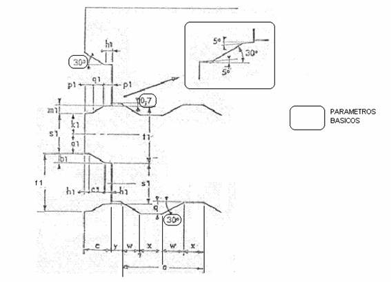
Figure nº 2
16º.- Pending length of the secondary scroll battlement: w = q / tg 30º
(w = 13.706 /0.57733 = 23.74 )
17th Length of the base of the secondary scroll’s battlement: x = (a – 2w) / 2
(x = (93.1 – 2 x 23.74)/2 = 22.81)
18º.- a1 = k – D/2 – F2 ( a1 = 80.624 – 92/2 – 1.8 = 32.824 )
19º.- b1 = k – 2 a1 ( b1 = 80.624 – 2 x 32.824 = 14.976 )
20º.- c1 = b1/ tg30º ( c1 = 14.976/0.5773 = 25.94 )
21º.- h1 = ( c – c1 )/2 h1 = ( 48 – 25.94 )/2 = 11.03
22º.- k1 = p – D/2 – F2 + 0.7 ( k1 = 81.894 – 46 – 1.8 + 0.7 = 34.794 )
23º.- m1 = p – 2k1 ( m1 = 81.894 – 2 x 34.794 = 12.306 )
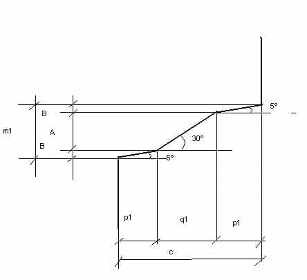
24º and 25º.- For the calculation of the heights p1 and q1 we will look at figure 3.
In it the following equation is fulfilled:
c = 2p1 + q1
m1 = 2B + A, B = p1 x tg 5º , A = q1 x tg 30º
Therefore m1 = 2p1 x tg5º + q1 x tg30º = 0.176 p1 + 0.5773 q1
Therefore the equation of two unknowns is posed as follows:
c = 2p1 + q1
m1 = 0.176p1 + 0.5773 q1
but since c and m1 are already known values, we would have:
2p1 + q1 = 48
0.176p1 + 0.5773 q1 = 12.306
if we solve this expression it gives us the following values:
p1 = 15.741 ql = 16.518
26º.- Calculation of elevation y:
Figure 2 shows that: Figure 2 shows that:
c + y + w – p1 = w + x + w, simplifying:
c + y – p1 = w + x, where:
y = w + x + p1 – c
y = 23.74 + 22.81 + 15.741 – 48 = 14.291
27º.- s1 = k1 + a1 ( s1 = 34.794 + 32.824 = 67.618 )
28º.- f1 = m1 + s1 + b1 ( f1 = 12.306 + 67.618 + 14.976 = 94.9 )
29º.- f6 To calculate this cut, we will rely on the figure No. 4. It is met:
1º) y = D/2 + F3 + F4 – F/2
y = 92/2 + 0.8 + 2.25 – 1.1/2 = 48.5
2º) x = V k*k + y*y
x = V 80.624×80.624 + 48.5×48.5 = 94.087
3º) f6 = ( x – D )/ 2
f6 = (94.087 – 92 ) / 2 = 1.0435
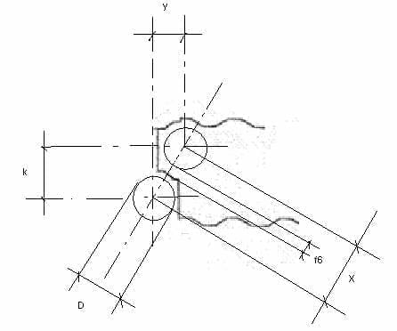
Figure nº 4
30º.- f7 . By reasoning analogous to the previous one we would have:
1º) x´ = V p*p + y*y
x´ = V 81.894×81.894+ 48.5×48.5 = 95.178
3º) f7 = ( x´ – D )/ 2
f6 = (95.178– 92 ) / 2 = 1.589
It is possible to prepare or get a small computer program for the calculation of all these values, without the need to operate by hand.
 DIE FOR ENDS
 SHEAR KNIVES
 MANUFACTURING PROCESS OF AN EASY-OPEN LID
 SPECIAL DIE FOR ENDS WITH INCORPORATED CURL
 DETERMINATION OF THE COURT FROM A ENDS
 EVOLUTION OF THE FUNDS PROFILE DIAMETER 99
 SPECIFICATION OF TIN FOR ENDS


0 Comments