
DESCRIPTION
The function of a die of lids is to die and form them from the metal strips that are fed to the press transversely to said die.
The dies are designed to be mounted on a press. The main dimensions of these are determined according to the type of press, for example its height, dimensions of the base plates, fixing holes, height of columns – if it bears them, etc. They are linked to the type of press on which they will work.
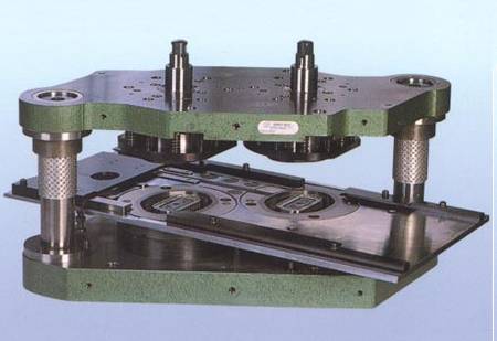
The design of the dies can be done with guide columns or without them. The decision to incorporate them or not, depends on several factors such as: accuracy required, quality – cost of the tool depending on its use, its life, type of press, etc. The most frequent is to equip the die of columns because their performance is significantly improved regardless of the press used. The number of columns is also a function of its application, the normal is three, although sometimes two are enough. In general, in this work it is assumed that the die is equipped with columns. (See figure 1)
Figure 1.- Die with columns mounted on press
Another factor that basically defines a die is the number of caps that can be made per stroke. So they can be:
– “Monopunzón” or simple dies, which make up a cover for each stroke.
– “Double dies”, equipped with a pair of punches and make two covers per hit.
– “Multipunzón”, which are equipped with three more punches.
Other die elements also allow several solutions. For example:
– Cutting ejector: Can be driven by springs or by compressed air.
– Lower pressure system: Can be operated by springs, rubber or tire.
In each case it is necessary to study which is the ideal solution. Let’s now describe each of the pieces that make up the die.
CUTTING PUNCH
Incorporated into the moving part of the die, it goes up and down with it mounted on the press carriage. The set of this moving part is usually also given the name of “punch” for being the same its most important piece. It is normally fixed to the “punch holder plate” by means of screws firmly and precisely. It has two missions:
– a) Combine with the “blade” to cut the disc from the fed material. The lid will be obtained from it.
– b) Make contact with the “ironing ring” and firmly hold the outer part of the metal between them while the cover is being shaped.
KNIFE
It is housed in the fixed part of the die, mounted on the press table. This fixed part is usually designated with the name of matrix. It is attached to the “base plate of the matrix” and its function is to cut, with the help of the “punch”, the metal disk. Also on the internal part of the cap makes the “ring” in its upward career.
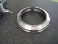
MATRIX CENTER
It has a ring shape. The wing of the lid forms on its upper part. The precision of its measurements is fundamental since it configures the main ones of the lid.
It is housed in the “base plate of the matrix” and is usually fixed to it by means of the “internal matrix center”.
INTERIOR MATRIX CENTER
It is located in the center of the lower part of the die – “matrix” – and internally to the “center of the die” and is used to form the profile of the lid together with the “center of the punch”.
CENTRO DEL PUNZÓN
The “center of the punch” is located in the middle of the upper part of the tool – “punch” – and presents an active surface with a silhouette contrary to the “inside inside matrix”, so that the conjunction of both pieces can form on the sheet the desired profile of the lid. Also fill the lid bucket.
BOTTING RING
The function of this ring is to press the wing area of the lid against the “matrix center” at the final moment of the descending travel of the press carriage. Another usefulness of this ring is the ejection of the die-cut top from inside the upper part of the die during the ascending stroke.
IRONING RING
The ironing ring helps to ensure a uniform height of the curl of the lid and to prevent wrinkles during the formation of the same, by applying a pressure against the surface of the lip of the “punch”.
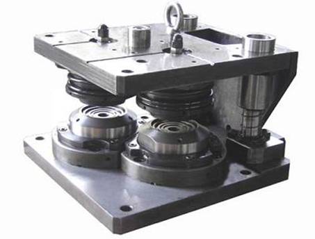
PRESSURE SYSTEM
The pressure of the “ironing ring” is generated by the lower system, located under the press table. It consists of an elastic element (gums or springs) that transmit their thrust to the pieces of the die by means of a disk equipped with rods that penetrate through the “base of the matrix” to the “ring presser”.
Frequently the elastic system is replaced by a pneumatic cushion, much more uniform in its work and a more precise adjustment.
EJECTOR
Each “cutting punch” is equipped externally with an “ejector” ring. This can be pneumatically operated or by means of springs, depending on the design. The function of the “ejector” is to keep the metal strips in their proper position while the lids are being punched and then to eject the cutout – or skeleton – of the “punch” lip as it goes out of the “blade”.
PORTA-PUNZÓN PLATE
On this plate are mounted the different parts of the moving upper part of the die: ejector, punch, puncher, center of the punch, shims, bearings of the columns … In turn this plate is fixed to the press carriage.
BASE OF THE MATRIX
The different parts of the fixed lower part of the tool are mounted on it: columns, knife, ironer, matrix center and interior of the matrix center. From it hangs the pressure system. At the same time, it is mounted on the press table.
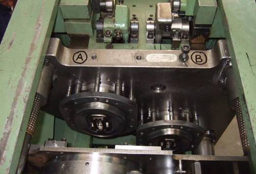
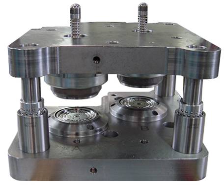
In the drawing a “double guided punch with columns” mounted on a press is appraised.
ASSEMBLY OF A TROQUEL
The elementary indications given below for mounting a die on the press are based on the following assumptions:
– The press is adequately maintained and therefore meets the conditions of parallelism between car and table. (See figure 2) Also the game in the slide of the car is correct.
– It is a die with guide columns, adjusted and ready to work.
Figure2 – Conditions to be met by the press
The logical process to follow is the following:
– Put the press on until it warms up slightly before mounting the die, approximately ten minutes.
– Make sure that both the bottom of the plate “base of the matrix” and the top of the “punch-holder plate” are free of dirt, burrs, shavings, etc. … Place the die on the table of the table , lower the carriage slowly until the “punch holder” can be screwed into it. Check that screws are used in good condition. Tighten in sequence and progressively.
– Slightly tighten the “base of the matrix” to the press table, lower the carriage until the punch is about 1 mm. from its inferior position.
– Match the slight clearance between guide columns and their bushings. It can be done with the help of a magnetic base comparator, placing it on the “punch holder plate” and the tip on the “base of the matrix”. By gently moving it to one side and another, you can determine the maximum game. It will have to average the same.
– Finish tightening the screws on the base and assemble the pressure system.
– Check by hand a cycle in vacuum and if everything goes well with material.
DIE MAINTENANCE
Periodically a die must be subjected to an adequate revision and depending on it take the corrective actions.
Each of the pieces that form the tool must be “in measures” in relation to the design plane. Given this of course, we will focus on the interrelation of each other in their assembly.
In this sense, in general, it is convenient to verify:
- a) Top :
Assemble the assembly: “punch”, “punch” and “punch center”. Set on a magnetic plate, check that:
1º)
– The cutting diameter (surface of the “punch”)
– The inner diameter of the “punch” lip
– The outside diameter of the “center of the punch” (diameter of the bowl)
They are concentric. Max error 0.01 mm (See figure 3)
Figure 3.- Check between punch, punch and center of the punch
2º)
In the “punch”, the back surfaces of the “punch” and its cutting edge must be perfectly flat and parallel to each other. Max error 0.05 mm The inner face of the lip of the “punch” – the one that forms the curl of the wing of the cover – must not show wear – increase in diameter – greater than 0.04 mm. If so, you have to rebuild the lip – yes, it allows it – or reject the piece. You also have to check the cutting edge if it keeps its edge alive or requires grinding. To maintain the height of the same, each 0.4mm of lost by grinding must be replaced with a shim.
The lip of the punch normally has a 30 ° inclination and must exactly match that of the ironing ring. For this, they must be rectified together, using the same adjustment of the grinding machine. The cutting edge should have a small flat and horizontal surface of 1.5 mm. approximately in width. The value of the cutting diameter must be maintained at least in a section of 2.5 mm, then it is usually lowered to reduce contact with the edge of the blade. (See figure 4)
Figura 4 .- Punch verification
The lip of the punch normally has a 30 ° inclination and must exactly match that of the ironing ring. For this, they must be rectified together, using the same adjustment of the grinding machine. The cutting edge should have a small flat and horizontal surface of 1.5 mm. approximately in width. The value of the cutting diameter must be maintained at least in a section of 2.5 mm, then it is usually lowered to reduce contact with the edge of the blade. (See figure 4)
3º)
The radius of the “punch center” that forms the cuvette must not be worn out – enlarged -. A wear greater than 0.1 mm. is not acceptable
4º)
The outer diameter of the “center of the punch” – diameter of the bowl – must not show signs of wear. Its value must not be less than the nominal minus 0,03 mm.
5º)
The depth from the “center of the punch” – flat part of the bowl – to the lip of the “punch” must be appropriate. If it is smaller, the bucket will be missing height. If it is greater, wrinkles in the wing can occur. (See figure 3)
6º)
On the “punch holder plate”: the “punch” and “punch center” housings must be perfectly concentric with each other. Its seats, parallel to each other and to the base of the plate. In the case of double die, the depth of analogous accommodation should be exactly the same. Check that the guide columns maintain their precise perpendicularity to the support surface of the plate on the press carriage.
7º)
The “ejector” of the cut must slightly protrude from the cutting edge of the punch. It will emerge approximately 0.4 mm. If this is not the case, the necessary adjustments will be made – depending if it is pneumatic or by springs – to achieve it.
In the case of “ejector” by springs, it will be checked that it and its axles do not show breakage or wear.
In the case of pneumatic “ejector”, the “O” rings must not wear or leak.
8º)
Check that the lip of the “drip ring” – contact area with the “matrix center” – is in good condition. If it is flat, check that it seats perfectly, using blue ink on “marble”. If it is of the curved type, check that the radius is in measure.
Check the parallelism between the surfaces: Rear part of the “botador” and lip of the same. If there is a lag greater than 0.01 mm, they should be corrected.
The “dropper” shank and its spring must be in perfect condition.
- b) Bottom
1º)
Plate “base of the matrix”: Its surface of support on the table of the press, must be perfectly flat. At least to present 75% support, doing the test with blue ink on marble.
The seat housings of the different pieces (blade, center of matrix) must be well parallel to the base of support and if it is a double die, exactly at the same height.
Verify that the bushings or guide column bearings are mounted perfectly perpendicular to the supporting surface and do not present any damage or wear. Clearances greater than 0.003 mm. with their columns, they make the whole disposable. (See figure 5)
Figure 5 .- Base of the matrix
2º)
Matrix center: Its inner and outer diameters (active on the tinplate) must be perfectly concentric, not presenting ovations or wear. The measurements shall be taken 1.5 mm below the radius and at least three points at 120º. Errors greater than0.02 mm. They make the piece rejectable. The interior and exterior spokes should not be enlarged by wear. They must not be greater than 0.1 mm.
The upper surface, the seat of the “interior matrix center” and the rear surface should be flat and parallel to each other. (See figure 6)
Figure 6.- Points to verify in the matrix center
Assemble the “inside of the matrix center” and check that the distance from the lip of the “matrix center” (upper surface) to the “inside of the matrix center” is the one specified. Variations in it would affect the profile of the lid to be obtained.
Mount on the “base of the matrix”, in its corresponding housings the “blade”, the “center of shade” and the “interior of the matrix center”. With the help of a dial indicator check the concentricity between the diameter of the cutting edge of the “blade”, the outer diameter of “matrix center” and the “inside of the matrix center”. The concentricity must be adequate.
3º)
Ironing ring. For each repair of the die, check that the lower seating surface of this ring – contact surface with the “spider” of the “pressure system” – is perfectly flat. It can be done on the “marble” by inking it. Rectify the same in case of deformation.
The upper lip of this piece to have the same inclination as the lip of the “punch”, on which it affects. The only way to ensure this is to perform the grinding of both lips followed by the same adjustment of the grinding machine.
When assembling the “ironing ring”, its upper lip will be approximately 0.15 mm below the cutting edge of the “blade”
4º)
Knife. We start from the assumption that it is carbide, because it is the most frequent case. Its handling to be careful, as any hit, fall, etc. it may involve the breakage of the carbide insert.
Check the concentricity between the cutting edge and its outer diameter – housing on the “base of the matrix” -. Check the state of the cutting edge, rectify slightly if required, 0.1 mm is sufficient. If the distance from the cutting edge to the lip of the “matrix center” has been lost with successive grinding, it can be redone with the use of shims on the blade, but always checking that they are free of burrs, flat and of a uniform thickness . The number of shims used should be kept to a minimum.
The clearance of the cut between the punch and the blade should be checked after grinding to ensure that it remains at 10% of the thickness of the metal for steel and 15% for aluminum
5th) Pressure system.
1) .- Superior surfaces of the “spiders” (shanks): The upper surfaces of the shanks must be flat, (this is achieved from the same grinding) and at the same level. The holes of the stems through the “base of the matrix” will be adjusted the same (without slack). The rods perfectly set square on the presser ring
2) .- Central axis. The same, once mounted, will be perfectly square with the “base of the matrix” and not present excessive wear.
3) .- Springs. Their ends must be closed, rectified squarely and parallel to each other. (See figure 7)
Figure 7 .- Pressure system
 DIE FOR ENDS
 DIE FOR EMBUTITION PACKAGING
 DEFECTS AND SOLUTIONS: TAPPING OF COVERS
 TYPES OF PUNCHES: DESIGN AND MAINTENANCE
 SHEAR KNIVES
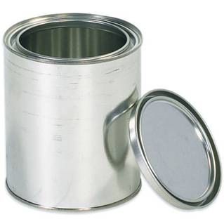 TOOLS FOR RING LID Paint containers
 SPECIAL DIE FOR ENDS WITH INCORPORATED CURL
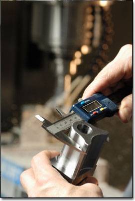
 CONTROL OF ENDS IN DIE
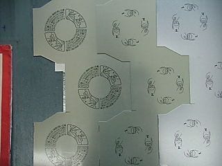 CALCULATING THE PROFILE OF A CUT IN ZIGZAG
 DETERMINATION OF THE COURT FROM A ENDS


0 Comments