the importance of following specifications: bodymaker top wall VS can neck forming process
We started this article to briefly show what can happen in a canmaking process when we allow variations or do not follow the specifications of the established process.
Each process is composed of raw materials, equipment and quality controls. The control of all this is what guarantees an excellent final product.
In the quest for competitiveness today, it is normal to make adjustments to raw materials, processes and process specifications with the goal of operational excellence. We can do this without affecting the final product.
Very important to note that any changes made in this chain, we must make the appropriate adjustments to meet customer specifications.
Once the process parameters have been defined, we will have to follow and control them effectively.
We will explain how the Topwall variable can directly affect the can neck forming process.
Before we get Topwall, we have some processes prior to it and some other processes with variables to control. We will describe some examples in the sequence below:
- Metal coil (conditions, thickness, postlub lubricant).
- Flake press (coil lubrication, air and vacuum pressures, general equipment alignment, tooling conditions).
- Decorators (Guarantee 100% coverage of external varnish, varnish layer within specification, controlled varnish viscosity, general cleanliness of equipment).
- Inside Spray (Guarantee 100% internal varnish coverage, varnish layer inside the specified, general cleaning of the equipment).
- Necking (Ensure 100% neck wax application, air and vacuum pressures within specified, tooling conditions).
We are considering that we have full control over these variables, so we can talk specifically about Topwall and its impacts.
Topwall is one of the variables we control in the can forming process and passes through the BodyMaker equipment.
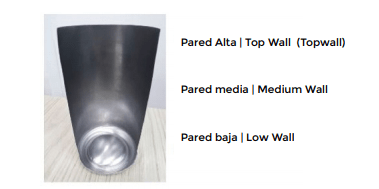
This is the last stage of ironing the metal, where we have the high wall section, the region where the neck of the can will be formed.
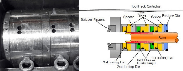
Below we have the image of the tool package, their respective die holders and spacers.
The sequence of the tooling is Redraw (drawing), First, Second and Thirddie.
In many companies they call the Second Die from Midle Die and the Third Die they call it from End Die. Important is that each one has its percentage of reduction during ironing.
Theoretical % of reduction % Theoretical reduction: : 3rd Die 38 to 40% – 2nd Die and 1st die 27% – Redraw Die 3%.
The punch advances and reaches the flake, which will be formed into a can and reduces its diameter in the Redraw operation without changing its thickness.
It goes through the sequence of ironing the metal on the 3 dies where the thickness is distributed progressively until the height of the can is reached.
Finally, the punch touches the dome which in conjunction with the nose cone making the bottom of the can. Here we have the smooth can without trimmer.
After the trimmer operation we have a smooth can in its standard height.
Taking into account the dimensional Wall checks we do on a smooth can we have:
To provide wall thickness values, take as a theoretical example this progression table below with Metal Specifications, Punch Step and BodyMaker Tooling Progression. Remembering that each plant has its own tool progression table.
The Topwall of the can needs to be set depending on the Necking tools.
If we are going to follow this specification of Metal, Punch Pitch and Tool Progression, we will result in a 0.0060″ Topwall. (Example)
Theoretically it means, that we should set up in our necking tools a gap between the tools that accepts this thickness of the upper wall.
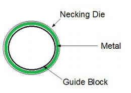
Necking equipment manufacturers are generally tooling suppliers and provide the tooling kit (Necking Die and Guide Block) according to the company’s engineering sector information, obeying these Gap and with the respective progressions established for the shaping of the neck of the can.
Considering an average value of 0.0060″, the necking tool can withstand a 0.0004″ variation of the top wall without major problems, since this variation comes from the forming process.
In this case we would have a specification of 0.0058 “min. 0.0060 “Med. 0.0062” Max.
By making sure the cans run within this range, we will have a controlled neck process.
However, this is not always the case. Imagine we have variations beyond these specification limits.
EXAMPLE 01
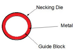
Let’s take a can with the topwall, varying the dimensional 0.0058 “Min and 0.0065 “Max.
In this case we have a high range of variation of 0.0007″ which exceeds the upper limit of 0.0062″, and an average of 0.0061″ which is also high.
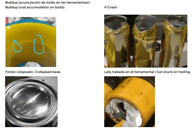
Note in the figure above, that the metal enters the tools with great interference, because it is outside the clearance range between the tools. The thicker points are subject to deformation during forming. This type of deviation can cause:
These are types of defects that allow the machine to operate, but with low availability.
Increases machine rejection due to canning, increases downtime due to Buildup and tool changes, deconfigures the work area due to the issue of order and cleanliness.
Identifying these deviations and acting immediately makes the process continuous.
EXAMPLE 2
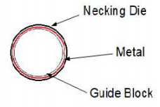
Let’s take a can with the dimensional Topwall 0.0053 “Min and 0.0059 “Max.
In this case we also have a high range of variation of 0.0006″ which exceeds the lower limit now which is 0.0058″, and average of 0.0056″, very low.
Note in the figure above, that the metal enters the tools with a large variation and clearance, outside the Gap range between the tools. The points with lower thickness are subject to deformation at the time of forming. This type of deviation can cause:
Wrinkles | Wrinkles:
These are types of defects that also allow the machine to function properly, but the rejection of the inspecting machine increases terribly, affecting the availability of the equipment. In most cases, these can inspection equipment have interlocks that, in times of high rejection, slow down and sometimes stop the equipment.
The neck forming equipment in general works at high speeds from the oldest to the newest, the operating speed varies from 2000 to 3400 cans per minute, for these reasons the control of the process chain must be fulfilled in a disciplined and routine way because any deviation can cause harmful impacts on the equipment.
With all processes under control, the Necking is an equipment that can deliver availability above 95% efficiency.







0 Comments