SUMMARY
Mode and means to control the quality of the curl of the domes for aerosol containers on which the valve is mounted.
PREAMBLE
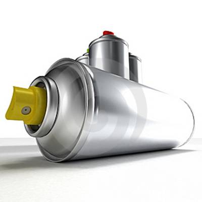
The aerosols are equipped with a metering valve for the product, which is attached to the top of the metal lid or container dome. The assembly of this valve is carried out by the packer, and therefore the manufacturer of the container, the valve and the filler are involved in its proper execution. The first two in the supply of some suitable components, and the third in its proper assembly.
It is particularly important that the hole where the valve is housed is properly dimensioned, and within very precise tolerances. This hole is standardized worldwide at a value of 25. 4 mm (1 “). The same is topped by a curl on which the valve is clincha. See figure # 1
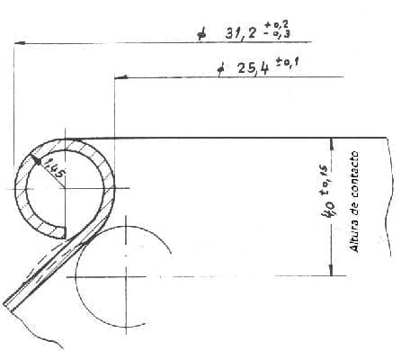
Figure nº 1: Curl for valve housing
The container manufacturer must assemble a quality control system so that this loop is within specifications. In this operation a material is used that is a particular case within the quality control for metal containers. We will define and describe the necessary gauges to use to implement the monitoring of the quality of the curl. The rest of the measurements of the dome are verified the same as if it were a normal cover and therefore we will not enter into consideration. In addition this issue has already been addressed on this website at work:
The measures to control over the curl of the dome are:
– Outside diameter of the curl
– Diameters inside the curl
– Thickness of the curl
– Valve contact height.
The tolerances indicated in drawing No. 1 are those reflected in the FEA 201 standard, but in practice they result in excessive sedimentation and must be reduced to 31.15 + 0.10 and 24.5 + 0.05
1º.- OUTER DIAMETER OF THE VALVE ROLL
The first check to be made is the outer diameter of the curl. It is done by means of a “pass-not-pass” gauge, ring type. The same is illustrated in figure 2
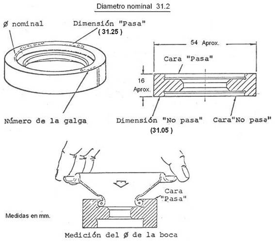
Figure No. 2: “pass-not-pass” gauge for outer diameter of curl
Just place the cone on the face “passes” and verify that it fits well and then on the face “does not pass” and see that it does not fit. If this happens, the piece is good, otherwise it is defective. On the figure 2 the action is appreciated.
2º.-INTERIOR DIAMETER
Pairing with the previous measurement, goes the verification of the inner diameter of the mouth of the aerosol cones. For this purpose, a special gauge type dial indicator with direct reading is used. Figure 3 illustrates the gauge and its accessory. As it is seen it consists of a probe that is introduced in the mouth of the cone, formed by segments that expand when the trigger is pressed. The accessory is an adjustment ring and zeroing, its internal diameter must be exactly the nominal value of the mouth of the cone.
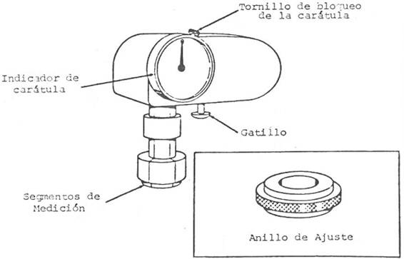
Figure nº 3: Cone mouth gauge
To adjust it, proceed as follows:
– Step 1: With the trigger depressed, place the measuring segments inside the adjusting ring and release the trigger.
– Step 2: Turn the dial to zero position and lock with the locking screw. See figure # 4
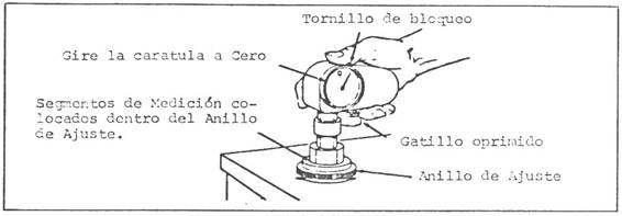
Figure nº 4: Adjustment of the gauge for cone mouth
To measure the mouth of the cone, with the trigger depressed, place the measurement segments inside the mouth and release the trigger. The differential reading with respect to the nominal reading will appear on the cover page. See figure 5
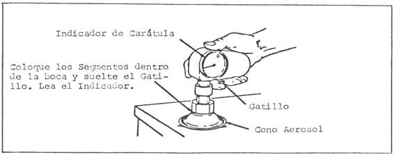
Figure nº 5: Measurement of the mouth of a cone with gauge
For a good use of the gauge, all its parts must always be kept very clean.
Gauges similar to that shown can be found commercially. In photo # 6 you can see an example.
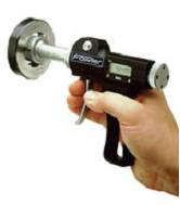
Figure nº 6: Valid commercial gauge for inside diameter of curl
Another simple and economical system for the control of the inner diameter, although with the limitation of not giving a direct reading, is the use of a gauge type “pass – does not pass”, as shown in drawing # 7.
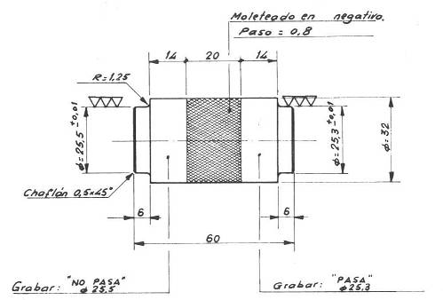
Figure No. 7: “pass-not-pass” gauge for inside diameter
The values of this gauge are given to comply with the FEA 201 standard
3º.- THICKNESS OF THE RIZO
For this data, a gauge is used that determines the dimensional quality of the curl thickness on the cones. Measure this thickness with an angle of 20º from the axis of symmetry of the container.
It is a micrometer gauge with a minimum path of 10 mm. Figure No. 8 illustrates the gauge with its different parts. It can be prepared from a micrometer to which a stop is added that positions the axis of the micrometer at 20º from the vertical and a grip ring.
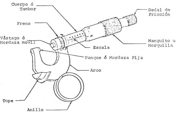
Figure nº 8: Special micrometer for curl thickness
The way of operating is as follows:
Step 1: With the brake in the “removed” position, adjust the micrometer so that the reading of its scale indicates an opening of approximately 5 mm. See figure No. 9.
Step 2: Insert the gauge into the curled mouth of the container, as shown in step 2 of drawing # 9.
Step 3: Put the index finger of the right hand on the ring and exert a slight downward pressure to insert the gauge.
Step 4: Firmly hold the micrometer and container with your left hand, so that the micrometer stop rests on the top and side of the curl.
Step 5: Close the micrometer by turning the friction thimble until the stem touches the curl. Record the reading on the corresponding report.
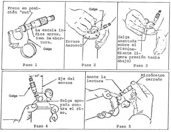
Figure nº 9: Different steps in the curl thickness measurement process
The gauge should be periodically adjusted to zero, following the typical procedure of this operation on a micrometer.
Another test alternative can be mounted, based on a “pass-not-pass” gauge. It is simpler to use, however it can only be used for a specific thickness of curl, while the previous one is valid for any thickness.
Figure 10 presents this gauge and its mode of use. Measure the thickness with an inclination of 30º. It is enough to prove that the curl is introduced without difficulty through the slot “passes” and does not enter through the “does not pass”.
The nominal value for the measure of curl thickness is 2.90 mm. diameter. A normal range of tolerances is + 0.15 mm. However, there are some curl designs that have a slightly oval shape, with their major vertical axis.
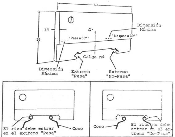
Figure nº 10: Galga “pasa – no pasar” for curl thickness
This type of gauges must be made in stainless material.
The good maintenance of all the previous gauges, requires to always keep them clean and free of foreign particles. If your use will not be very frequent, periodically apply a light film of machine oil.
4th.- CONTACT HEIGHT
The fundamental function of the hole in the dome is to serve as a housing for the valve that supplies the contained material. For this reason it is important to check that the point, or better circumference, on which the valve is located is correctly positioned in height. Suitable tools for this are Boxal type I and II gauges.
Boxal type I : It is specially designed for the measurement of the height of curl, which is the same used for the determination of the depth of clinching of the valve.
Boxal Type II : It is used to check the quality of the curl, as an absolute measure, and if necessary, to determine the value of the curl height.
The basic idea of the Boxal gauges, is to make a functional and practical measurement, that reflects in a precise way the conditions of chinchado. When the dimensions of the tracer of the Boxal gauge and the actual clinching contour are identical, the depth of clinching with this gauge can be determined (Boxal type I) The accuracy of the measurement is based on the previous comparison of the gauge by means of A standardized calibration ring and also depends on the manufacturing precision of the gauge.
The principle of operation of the method is indicated in figure No. 11.
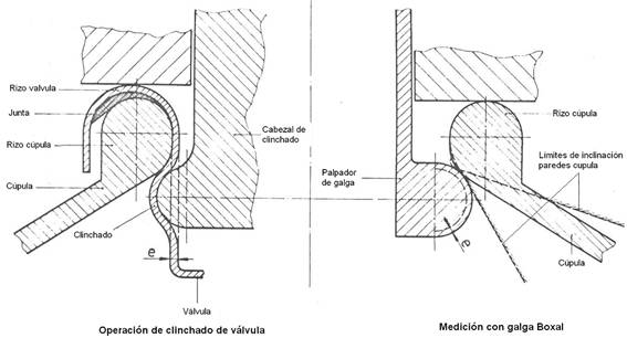
Figure nº 11: Operation of Boxal gauge
It is a matter of comparing the actual clinching height with the nominal one and checking that they coincide. In this figure, on the left side is drawn the clinching operation of a valve of thickness “e” on the mouth of an aerosol – in this case of monobloc aluminum manufacture -. On the right side is the previous measurement of this same mouth at the clinching point, the feeler gauge has been increased with the thickness “e” to simulate the same conditions in both cases. . The read variations will indicate the error in the clinching operation, taking into account the joint and metal thickness of the valve.
Measurement with Boxal type I gauge:
The gauge must be calibrated first by adjusting it by means of the calibration ring, as indicated in figure 12, left part. This ring leaves the gauge adjusted for a theoretical contact height according to the specification or standard used. In our case 4 + 0.15, as indicated in figure # 1.
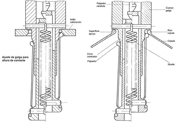
Figure nº 12: Adjustment and use of Boxal type I gauge
Once inserted into the calibration ring, the dial of the gauge is adjusted to 4.00 mm. The measurement on the container is done in an analogous way, see figure 11 on the right hand side, for this, pressing the gauge button, we place it inside the mouth of 1 “(25.4 mm) and slowly loosen the button. This measurement is repeated three times, each time rotating the container about 40 °. The smallest measure of the measurement is taken as the value of the clinching depth.
Measurement with Boxal type II gauge:
To the left of illustration No. 13, an elevation of this gauge mounted on the mouth of an aerosol container is presented. In plant a section of the same appears by the area of taking measurements. The primary use of this gauge is for checking the uniformity of the curl along its circumference in the clinching zone.
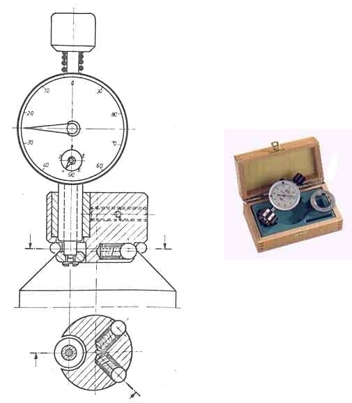
Figure nº 13: Boxal gauge type II
This measurement is carried out, as in the case of type I gauge, by pressing the gauge button and introducing it in the opening of 1 “(25.4 mm) of the container by means of a turning movement. The lack of uniformity that appears in the readings should never exceed a previously fixed limit value, and that depends on the type of closure applied.
Three measurements are made with the gauge, the container having to rotate 120º in relation to the gauge in each of them.
The calculation of the height (CH) of contact – which is done in clinching – must be calculated by means of the formula:
CH = (Hmax. + Hmin) / 2 + ½ | 25.4 – (Dmax + Dmin) / 2 |
In which:
Hmax = The highest value of the measurements made on the curl in question, with type II gauge
Hmin. = The lowest value of the measurements made on the curl in question, with type II gauge
Dmax. = Maximum internal diameter.
Dmin. = Minimum internal diameter.
To the left of illustration no. 12, a boxal gauge type II commercially available with its adjustment ring and inside its case is shown
Advantages of application of Boxal gauges:
The use of these gauges and the proposed method have the following advantages in relation to the use of other measurement systems.
1º.- The contact with the curl height of the dome allows determining the depth of the valve’s clinching taking into account other factors such as the thickness of the material and the thickness of the joint.
2º.- The required knowledge and necessary care for the use of these gauges are minimal.
3º.- The possible variations in the shape of the curl of the dome (inner diameter, inner radius and angle of the shoulder), and in the accuracy of the radius of the clinching tool, have very little influence on the accuracy in the measurement of the curl height.
 measuring gauges can manufacturers
 quality control in the manufacture of metallic containers
 OVERCAPS FOR AEROSOL PACKAGING
 DIMENSIONAL CONTROL OF THREE PIECES TYPE PACKAGING
 EVALUATION OF EXPULSION OF THE PLUG IN PAINT CONTAINERS
 CALCULATION OF THE TABS OF MADE A FLANGE
 PERFORATIONS FOR GOLLETES / PLUGS
 DIMENSIONS FOR CUPPAGES OF ENERALED AEROSOLS
 AEROSOL CUPS


I am looking for thread go and no go for the right R134a & left R1234yf valve and caps on refrigerant cans