SUMMARY
Basic principles of electric welding by points in the metal industry and criteria for a good formation of the welding point.
This work summarizes and complements the one already published on this Web page under the title:
DEFINITION
In the metallic cans welded by means of electric welding, the welding point is obtained between the two metallic parts to be joined, without any external contribution, it is enough the passage of an intense current through these metallic pieces, in the area considered to adhere .
The heat necessary for welding is produced by the resistance that the material opposes to the passage of this current at the point to be welded.
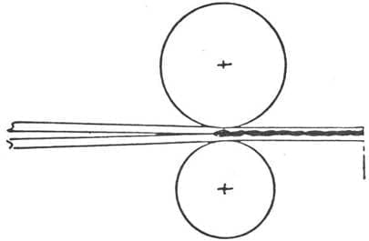
A continuous welding line is achieved by means of a succession of points that are produced between the two metal pieces to be joined, subjected to the pressure of two circular electrodes, through which the electric current circulates, animated by a movement of rotation in the direction reverse. See drawing # 1:
Figure nº: Formation of a continuous welding line
BASIC PRINCIPLES
A.- Notion of electric current: Ohm’s Law
The current intensity, measured in amperes, in any electric circuit, is equal to the voltage, measured in volts, at the terminals of the circuit, divided by the resistance, in ohms, of said circuit:
I = V / R
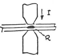
See figure # 2:
Figure No. 2: Schematic of a welding spot
B.- Notion of heat: Joule’s Law
The amount of heat produced in a conductor by the passage of an electric current depends on:
– the current intensity I
– the resistance of the driver R
– of the time the current circulates t
all linked by the expression:
2
W = 0.24 R I t
C.- Resistances in the welding equipment
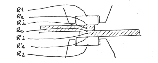
The following resistors are present in the welding circuit:
– R1 = Resistance between the upper sheave and copper wire
– Re = Resistance between wire and metal
– Ri = Internal resistance of the metal (1st zone)
– Rc = Contact resistance (interfaces)
– R’i = Internal resistance of the metal (2nd zone)
– R’e = Metal resistance / copper wire
– R2 = Thread resistance / lower sheave
See figure # 3:
Figure nº 3: Resistances in the welding circuit
The resistances Re, Rc and R’e, are variable depending on:
– the welding pressure between the electrodes (sheaves)
– the state of the surface of metals
– the shape and dimensions of the electrodes
– the material of the electrodes
– the surface state of the electrodes.
The resistors R1, Re, R’and R2 , are parasitic resistors, and produce the following energy losses:
Wp = W1 + We + W´e + W2
The resistors Ri, Rc and R’i are effective resistances for the formation of the welding point and cause the energy:
We = Wi + Wc + W´i
Observations:
a.- The energies W1 and W2 increase depending on the dirt and the deformation of the grooves of the welding rollers.
b.- We and W’e heat the metal surface and contribute to the oxidation of the weld. The amount of oxidation generated is a function of time and temperature.
D.- Energy balance
The energy consumed is: Q = We + Wp
The amount of heat necessary to reach the welding temperature is a function of:
– the volume of metal. See figure nº 4. This volume is:
V = 2e x c x vs. Being vs the welding speed.
Figure nº 4: Volume to be welded
– the specific heat of the metal
– heat losses.
These heat losses are:
– By conduction in the electrode, depending on:
o The surface of the electrode
o The contact between metal and electrode
o Weather
– By conduction in the welded metal, depending on:
o The thermal conductivity
o The thickness of metal
– By radiation
– By cooling the cold water of the rollers.
E.-Main functions of the welding pressure:
1.- Keep in contact the materials to be welded
2.- Prevents the arrival of air to the welding zone
3.- Forces the electric current to pass between the surfaces in contact
4.- Maintains a constant air contact resistance
5.- It causes a deformation of the metal crystals, by forging
6.- Prevents the formation of bags and porosities in the welded area
7.- Ensures the recrystallization of the welded metal, when cooled
8.- Prevents the expulsions of molten metal, during welding
9.- It allows the drag of the rotating sheave
Conclusion:
The ideal welding circuit must be designed in such a way that:
– The energy losses – Wp – are minimal
– The amount of oxidation generated is minimal
– The effective energy – We – be maximum
– The structure obtained is homogeneous
METAL CARACTERISTICS
The materials used in electrically welded cans are made from low carbon steels. Its content in C is < to 0.5% and < to 1% in other elements.
The influence of the different elements that enter with the iron to form the steel cause different effects such as:
Carbon : The hardness of the steel surface tends to increase with the carbon content. It has no significant effect on welding for C < 0.2%.
Manganese : Increases hardness and resistance to breakage. If Mn> 0.6%, in the presence of a high carbon content, the solder is brittle. If Mn <0.3%, porosity occurs and the weld becomes brittle. Therefore the Mn must be in a% between the two limit values.
Sulfur : Its presence should be 0.035% if possible, and never exceed 0.05%, as it would produce a risk of causing weaknesses in the structure of the weld, especially if the carbon tends to increase.
Silicon : 0.01% to 0.10% improves weldability.
Phosphorus : It is an impurity that should be presented in the least amount possible. It does not have to exceed 0.04%. Welding becomes brittle, causes fractures, reduces resistance to shock and fatigue.
Influence of surface coatings:
Tin: The superficial tin of tinplate reduces the resistance at the interface, so it is necessary to increase the welding current depending on the content of superficial tin, that is, its coating. Another aspect is that the higher the tin content, the greater the surface contamination of the electrodes.
Chromium: Treatments based on chromium and chromium oxide oppose the passage of current and are not suitable for electric welding.
FORMATION OF THE WELDING POINT
A.- Variation of the contact resistances (Re, Rc and R’e)
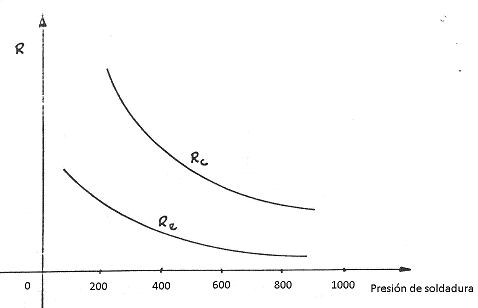
1º.- Pressure function:
– If the welding pressure is increased, it causes:
o A decrease in parasitic resistance Re and R’e
o A decrease in the resistance of the Rc interface
See figure nº 5:
Figure nº 5: Variation of the resistances as a function of the welding pressure
– This decrease is a function of:
o The nature of the surface
o The hardness of the materials
o Its conductivity
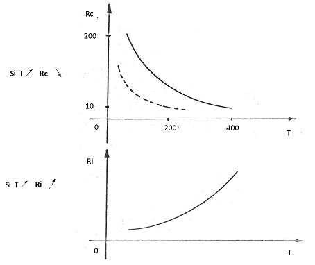
2º.- Temperature function:
– Under the effect of the temperature T , there is a softening of the asperities of the surface, a decrease of Rc (contact resistance) and an increase of Ri (internal resistance of the metal)
See figure # 6:
Figure nº 6: Variation of the resistances as a function of temperature
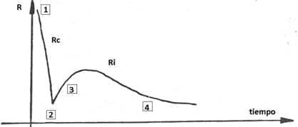
3º.- Evolution during the course of welding:
– 1) During the start of the welding, the most important energy consumed is caused by the resistance Rc.
– 2) Rc decreases towards 0, before the melting point
– 3) Ri is increasing to the melting point
– 4) After Ri decreases when the volume of the point increases
Graph 7 shows the evolution of total R by the action of Rc and Ri during the welding of the point.
Figure nº 7: Variation of the resistance as a function of welding time
Rc acts as a catalyst at the beginning of the welding process and allows Ri to be increased .
Re and R’e (resistance between metal / copper wire) are the source of lost energies, whose value is weak but does not vary during welding, provided that the electrode is a good conductor and is sufficiently cooled.
B.- Intensity of the welding current – welding time:
For the phenomena described in point A to redevelop well, it is necessary:
– A high intensity I
– A welding time Ts , brief.
2
Recall that according to the law Joule (W = 0.24 R I t) the energy consumed W is a function of the current I of the current and welding time t , with equal resistance R. Therefore the same value of W can be achieved with :
– I weak x long
– I strong x short t
If we choose the weak I option, it occurs:
– The temperature of the metal assembly rises but without reaching fusion.
– The losses increase
– The electrodes deteriorate
In all cases, the thermal balance will be much higher, as:
– I was , on the rise
– T weak, decreasing
It is admitted that the welding time is inversely proportional to the square of the current.
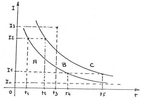
The diagram of the welding energy ( W ) as a function of the intensity ( I ) and the time ( t ), is reflected in the following graph No. 8:
Figure nº 8: Welding energy diagram
In which we can define the different zones as:
– Zone A = Metal gluing zone
– Zone B = Metal welding zone
– Zone C = Zone of external projections to the point of the metal
Practical way to adjust a welder for a given metal and weld pressure:
– The welding diagram must be built, looking for:
o The bonding limit
o The projection limit
All this for a specific tap of the transformer. The same operation is then performed for the next higher and lower take.
Three welding zones are obtained, from which we will choose the largest, regulating the machine to 50% of it.
C.- Influence of the dimensions of the welding point
The factors that affect the dimensions of the welding point are:
– The thickness of the metal
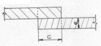
– The value of the overlap of the edges, which we designate by C
– The length of the welding point L , which is a function of the welding speed vs.
The most favorable conditions are given when L / C = 1. At a point like this, the heat of the weld is correctly distributed and a uniformly hot dots chain is obtained.
If L / C = 2 , the conditions are not so favorable, because at this point the heat of the weld is poorly distributed, and an alternative succession of hot spots and stuck (cold) points could be obtained. See graphic nº 9
Figure No. 9: Welding point diagrams
METALURGY OF THE POINTER WELDER
1º.- Heating period:
– The passage of the current gives rise to a localized heating, which reaches the fusion of the material corresponding to the two pieces
– During the heating, the lentil of material expands, understanding as a lentil the zone of molten material, which has this shape.
– A high compression force is required to neutralize the pushing force of the molten metal.
– If the compression force is too weak, the metal escapes in the form of projections.
– This results in important internal defects (cavities, pores …) in the welding.
2º.- Thermal state of the point, when cutting the welding current:
– Zone A = Metal in fusion
– Zone B = Pasty metal
– Zone C = critical temperature
– Zone D = Less than the critical temperature
– Zone E = Ambient temperature
See drawing nº 10:
Figure nº 10: Thermal state of the welding point
– The temperature gradient goes from 1,500º C to the ambient temperature in a few millimeters.
– Cutting the welding current marks the beginning of cooling.
3º.- Cooling phase:
– The core of the molten metal is in a large cooling mass, consisting of:
o The welded pieces
o The electrodes, which are cooled
– The heat exchanges are fast
– The crystallization is carried out converging towards the center of the point:
o Zone D = No structure change
o Zone C = The grain is refined
o Zone B = Fine structure
o Zone A = Fine structure
In the case that cooling is not carried out correctly under the welding pressure, the formation of blowholes may occur. The thermal contraction can also give rise to internal tensions at certain points.
EXAMINATION OF THE WELDING CIRCUIT
1º.- Problems posed by welding
– Geometry of the internal welding.
The internal welding is always irregular, and presents waves, molten metal, sharp edges, all of which is detrimental to good protection by means of the coating varnish.
– Homogeneity of welded metal
o An increase in welding speed or
o A reduction of the overlap value of the seam at equal speed
produces weaknesses in the welding, which are materialized by breaks in the internal welding
2º.- Description of the welding circuit
Consider the normal welding circuit, which mainly comprises:
– The upper sheave (large diameter)
– The lower sheave (small diameter)
– The welding transformer
This circuit is characterized by the fact that the two sheaves are of different diameter, so the contact surfaces are different, which implies:
1º.- R2 <R6 and therefore W6> W2
This means that the weld is hotter inside than outside.
2º.- In addition, the points already formed maintain a certain higher temperature in the part already made of the overlapped joint, which in the rear part still does not realize that it will be colder.
3º.- Since the wire remains for a longer time in contact with the external electrode, the external welding will be cooled more quickly.
It can therefore be said that the temperature distribution is asymmetric, decreasing from:
– The inside to the outside
– The front to the back
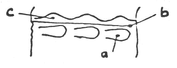
An examination shows that the point on the inner side of the weld is characterized by the following three elements:
– a) The footprint of the point
– b) The edge of the sheet edge
– c) Festoon of molten metal, pushed out of the weld.
Veer figure nº 11.
Figure nº 11: Elements of the internal face of the welding
3º.- Consequences:
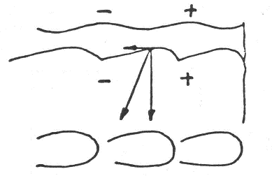
A cross section of the weld shows that the weld point forms a ridge forward (hottest part), since:
1º.-The deficient distribution of temperature has the consequence of leaving metal in pasty state between two consecutive points of the weld, this metal is stressed by the sheave at the moment when the next impulse is printed to the weld.
2 .- This metal that is pushed, is not subjected to the pressure of forging, nor is cooled by the sheave, so there is a risk of lack of homogeneity in the weld.
3º.- If the welding conditions are such that the L / C ratio is unfavorable:
– Sticky points are created between the hottest points.
– Increase the deficient distribution of energy.
Consequently, the metal in pasty state is stressed by the sheave creating a point stuck but not welded.
4º.- Dilation of the metal caused by heating can not occur vertically, being horizontally in the area where the ridge is formed. Therefore, after cooling, a contraction and a zone of tension is created in the region of the weld which presents a risk of fragility.
See figure nº 12:
Figura nº 12: Tensions in the welding after cooling








In welding of thin DR material like 0.16mm the weld at lead and trail ends gets cracks in post operation of flanging …what could the cause in relation to machine electrical design related to frequency drive , or current settings
Good morning Satish,
if you wish you can join the WhatsApp groups of Mundolatas, a colleague will be able to help you.
You can send an email to whatsapp@mundolatas.com with your name, position, company name and phone number with country code.
we will include you totally free and there you can exchange information and experiences with other workers.
Best regards