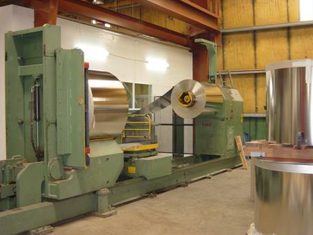
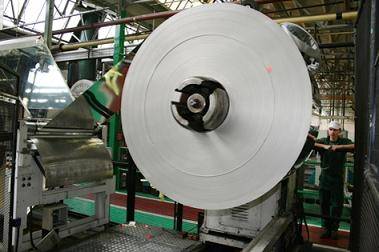
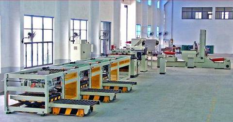
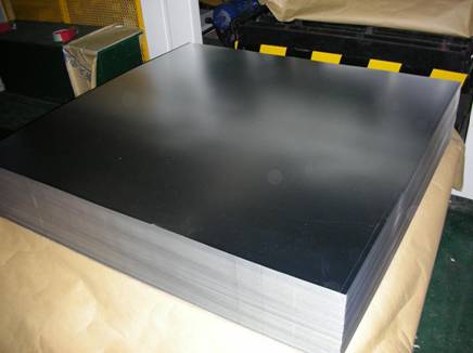
It is increasingly common for the container manufacturer to buy the metal to be used (tinplate, TFS or aluminum) in coils. This allows them a better use of it. In order to prepare this material properly, it is necessary to use a coil cutting line that may be your property or to use third parties to carry out this operation.
In any case, it is necessary to implement a quality control system to guarantee that the operation is carried out properly, both in the cutting operation and in the selection of the different qualities that are generated during the process. In this paper we will try to define the main parameters that must be controlled as the means to be put into play for it.
The cutting lines are supplied with a series of adjustment and control means to adjust them to certain working conditions – length and width of cut, range of thickness of the material to be given as good, hole detection, etc. -. We will not detail the same as they vary greatly from one case to another. They can switch between more or less manual adjustment systems to others fully automatic.
Let’s go into the detail of what can be the normal sequence of control of a coil throughout its cutting operation.
The parameters to be controlled can be divided into two groups:
1º.- Those that can be easily verified at the foot of the line
2º.- Those who, due to their complexity or the means to be employed, are required to make them in other points.
LINE FOOT CONTROLS
IDENTIFICATION OF THE COIL
Before proceeding to unpack the bobbin it is necessary to determine visually:
1) If each coil is accompanied by its corresponding ticket from the steel industry.
2) If the ticket is properly filled out.
3) If the same corresponds to the work order in progress, checking that the width of the coil, thickness, tempering and tinning are correct.
If the check confirms that all the data matches the expected data, it will be unpacked.
ASPECT OF THE COIL
Once unpacked, it must be visually verified that it has no defects.
1) Check if the coil is knocked or rusted or has another type of visual defect. If these exist, the coil will be removed in case it is necessary to submit a claim to the steel industry.
2) In case of minor defects -oxide only outside or minor blows- a special follow-up will be made during the first 100 meters. If the defect remains, the cutting process will stop.
CUTTING LENGTH
Once the change of cutting format has been made, to check if the adjustment of the line with regard to the length of the blade to be cut is correct, proceed as follows:
1) Cut only one sheet and stop the line. Place the sheet on the control table and use a graduated quality rule, with a precision of 0.5 mm. it will be verified that the length of the sheet is correct.
2) If this is correct, the next operation will be carried out. Otherwise, the error will be corrected, such as the verification of the cutting step roll or other adjustments.
LEAF WIDTH
At the same time that the cutting length is checked, the coil width and the same means – millimeter rule – and the same frequency must also be verified. It must take into account the margins that steelmaking standards apply to this measure.
The width must be measured in the middle of the sheet and perpendicular to the direction of rolling, the same being on the control table.
THICKNESS OF THE MATERIAL
Usually the cutting lines are equipped with an automatic and continuous system for controlling the thickness of the material. This system can be regulated between a range above and below the nominal value, in such a way that the leaves whose thickness is outside this range are rejected. Therefore the verification of the thickness is done automatically.
The regulation of the amplitude of this range and the definition of the limit thickness will depend to a large extent on the destination of the material. There are uses that allow a wider range of sizes than others. This value must be previously defined by the Quality control department.
However, since the measurement of this thickness is always done in the same position of the sheet, it is convenient to check manually at different points of the sheet – center and edges – if the size is kept uniform. This operation can be done once per coil.
It is evident that in case the actual thickness is outside of specifications it must stop and pass the corresponding claim.
PROFILE AND ARCH OF THE LEAVES
We define as a profile of a leaf the curvature that it presents in the longitudinal direction – that of rolling – placing it in vertical position and resting freely on its longitudinal edge.
We define as a leaf arch the curvature that it presents in the transverse direction – cutting edge – placing it in a vertical position and resting freely on its transverse edge.
Both values are controlled by measuring the arrow that said curvature generates. The maximum reasonable value is 30 mm. It must be verified at the beginning, middle and end of each coil. If a weld is present in it, it will also be checked after welding. The check can be done with the line running.
A simple way to control these two concepts is to draw on a rigid plate – or on the ground if it is in good condition – two red lines parallel to each other at 30 mm distance. Position the sheet vertically on this board with your hand taking it in half. Match the extreme edges of the sheet with one of the two red lines, if the center part of the sheet does not exceed the other red line, the profile will be valid. Turning 90º the leaf we will measure by the same procedure the arc.
An excess of values can usually be corrected by acting on the line leveler
CONTROL DESK
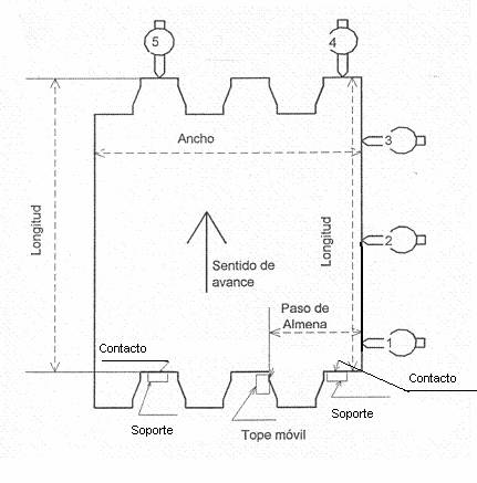
Before continuing with the following measurements we will describe the control table. It is an auxiliary equipment of the line, which consists of a board on which five comparative clocks are coupled, three in the direction of advance of the material and two perpendicular to it. See drawing below. Initially all of them must be set to zero, using a metallic square used as a standard. For the following checks, the blade must be positioned so that the part corresponding to the fixed side of the machine is placed on the right. It will rest on two rigid supports that coincide with the cutting edge.
Control desk
IT IS SQUARE
The aim is to verify that the length of the blade, on its fixed side, is square with the cutting edge – width of the blade. This verification must be done at the beginning of a change of format on the line. To do this, place the cut sheet on the control table as indicated in the drawing and check that the reading difference between the comparator clocks 1 and 3 does not exceed 0.5 mm.
If the difference is greater, it will be necessary to act on the settings of the equipment, focusing mainly on the way of working of the feeder roller, the guide of the coil and the longitudinal arrow of the blade.
DATE OF LONGITUDINAL CUT
Check if the fixed edge of the sheet is a straight line and therefore has no undulations. It is also checked on the control table and simultaneously to the square and with the same frequency. The comparator clock 2 must have an intermediate value between clocks 1 and 3, also fulfilling the condition already indicated that the difference between 1 and 3 does not exceed 0.5 mm. If these conditions are not realized, the edge of the coil is wavy and the arrow of these corrugations will be marked by clock 2.
FOOD STEP
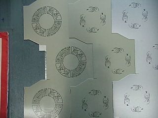
This is a specific feature of the zigzag cut, for sheets intended for container funds. It is examined in this case if the zigzag cut is correctly positioned in relation to the fixed and straight edge of the blade. For this, it is necessary to place a mobile stop on the control table, whose distance to the fixed edge corresponds exactly to the step of the battlement, See drawing. For the positioning of this stop, a standard template prepared for each type of zigzag cut is used. The comparator clock 1 will be set to zero with the standard template.
Positioning the sheet on the control table, the comparator 1 to give a reading that will indicate the positioning error of the step of the battlement, it must be within the tolerances field marked in the manufacturing standard.
OUT OF LINE CONTROLS
There are certain tests that require more complex means or due to their execution time, which are not adequate to perform at the foot of the line. They are really important and if you have the equipment to carry them out, it is good that they are made. These are:
QUENCHING
It is a fundamental fact to confirm that the tinplate that is in the process of being cut has the specified hardness. The check, if it is a tinplate of the “simple reduced” type, is done with a durometer adjusted to the HR 30T scale. It is preferable that this equipment is located in an appropriate enclosure – such as in the Quality Laboratory -, away from vibrations, noise, dust and shock. That is why the determination of hardness is usually done away from the line. Therefore, some test tubes have to be taken from the coil for this purpose. To avoid confusion, you have to mark them with the data of the coil to which they belong. We do not enter into the description of this test since the management of the durometer is supposed to be well known.
ELASTIC LIMIT
When it is a tinplate of the type “double reduced” it is not reliable to measure its hardness with the help of a durometer. The little thickness of these types of tinplate, make the penetration ball of 1/16 “, when nailing also deform the material, falsifying the reading.
Therefore, in this case it is better to measure the elastic limit, a fact that the steel industry provides as an identifying element. This test does require more complex equipment and high price, so it is difficult to do it continuously in each coil. There is the possibility of replacing it with a simpler one, using a simple tool that tests the elasticity of a specimen of well-defined dimensions. The specimen is bent over a small mandrel and then released. The residual angle of the deformed specimen is then measured. The value of it is carried on tables that determine the elastic limit fairly closely. This test is defined by the name of “spring back angle”. There are commercial teams in the market that allow their realization. Soon we will return to this topic in a monographic work about it.
TINNING
If it is presumed that there may be problems with the tinning of the coil, it will be convenient to check the same. Its realization is a typical laboratory test. There are equipment in the market for its realization, but if you do not have any of them – a frequent thing given its cost – you can resort to a slow but simple test like the one described in the work already published in this section under the name : DETERMINATION OF THE TOTAL TUNA COATING IN THE TIN WITH THE HEAVY LOSS METHOD (CLARKE METHOD)
These last three tests present the difficulty that it is practically impossible to perform them simultaneously with the beginning of the cut of the coil, since it will probably be cut before it takes time to perform them. Therefore, if anomalies are detected in them, the solution is to present a claim with the material already cut.
CLASSIFICATION OF DEFECTS
The cutting lines present the possibility of deriving the sheets detected automatically or manually as defective to different stackers. The number of them is not very large – two or three – so it is necessary to group different defects in the same stacker.
The logical thing is always to reserve one with perforated sheets, since it is the most dangerous defect, another one with tin-plating defects and a third one with outside caliber. Depending on the destination that will be given to the rejected sheets, this classification criterion can be modified.
————————————————
As a final consideration on the quality control of a coil in a cutting line, it is always an effective tool to have at hand the international standards on supply of coils by the steel industry. (UNE, ISO, SEFEL, etc) or the particular rules agreed with the supplier.





0 Comments