
SUMMARY
A machine is described that is capable of orienting and feeding an automatic seamer, revolving tops in the shape of a cone, at a rate of 9000 units / hour. It is a good example of mechanization. This option does not cancel the possibility of hand feeding the aforementioned lid to the seamer.
INTRODUCTION
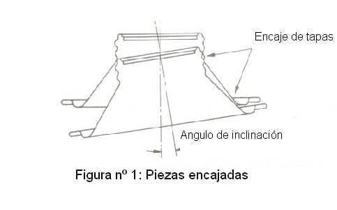
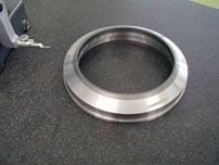
The cone shape in caps with a threaded neck, makes it difficult to feed into a seamer. They are not grouped or stacked naturally and when they are stacked, the adjacent tops tend to fit as they lean over one another. See Figure No. 1. Several feeding methods have been tried in the past in an effort to eliminate this problem.
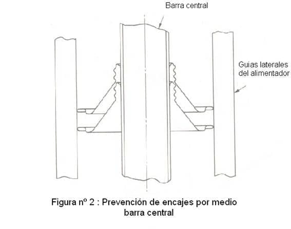
One of the solutions involved operators placing the lids on a central bar, which was then loaded into the cap stacker of the closing machine. The bar acted as a central locator guide, which prevented the undesirable lace of the lids. See figure nº 2.
Another method currently used is for an operator to place the caps, correctly oriented, inside a sloping channel, which is connected to the capper stacker of the seamer. This channel has a vibrator, to help the downward movement of the funds along the same, without producing lace.
Both methods have the disadvantage of being a laborious task, which limits the speed of production. In addition, an inclination of one component in relation to the adjacent one can cause jams, especially in the exit of the stacker of the machine, reducing the efficiency of the production line.
The work detailed here has allowed the development of a unit, which accepts cone-shaped lids without order, and supplies them correctly oriented to the seamer’s feeder.
EQUIPMENT DESCRIPTION
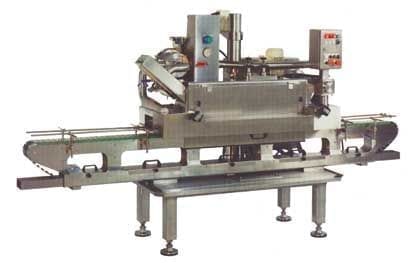
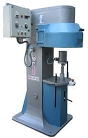
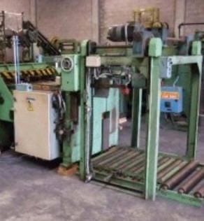
Figure 3 shows an overview of the equipment.
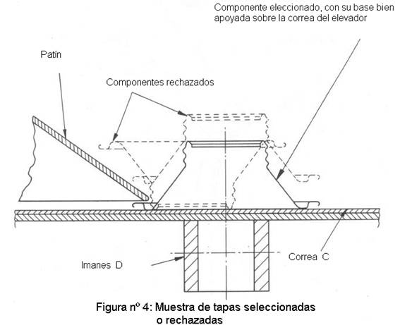
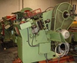
It consists of a tank (A), the capacity of it is approximately 1600 caps, (10 minutes of production working at 9,000 containers / hour). A part of the bottom (B) of the tank, placed in front of the belt elevator (C), tilts vertically approximately 40 mm.and shakes the covers, preventing them from blocking. Magnets (D) mounted behind the elevator belt, attract the lids towards it. The lids are transported on the belt outside the tank. The band travels at 33 m / mi and moves continuously. On the belt of the elevator, a sequence of runners and doors (or portlights) are positioned, which ensure that only the covers with the base of their bucket perfectly resting on the belt follow their path. The rest of badly positioned caps, return to the vat. See figure # 4
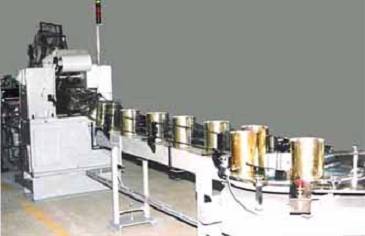
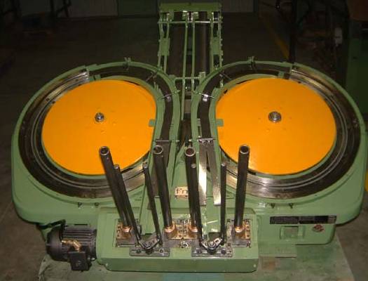
The last part of the guide deflects the covers to one side of the belt, ensuring that they are spaced apart, along the horizontal portion of the conveyor. The magnetic pulley (F) transfers the caps from the elevator belt to the stacker (G), which is curved in the manner of a shepherd’s crook. The guide rods (H) extend from the magnetic pulley, and ensure that the curl of the lid is attracted against said pulley, and is correctly oriented to transfer it to the stacker. See figure nº 5.
The shape of the stacker allows the lids to freely support and position an inner guide (J), that is, it is kept floating, resting on the covers. This guide facilitates the passage of the lids through the stacker at the necessary rate, for this it receives the help of a vibrator (K) mounted on the stacker.
As this inner guide (J) is supported and positioned by means of the covers in the stacker, the lower level and the upper one thereof must be controlled, for which two sensor heads (L) and (M) are used. The sensor (L) controls the upper level, which acts when the feed from the belt elevator exceeds the speed of the seamer. In that case the accumulation of caps in the stacker, covers the sensor head (L). It acts electrically on an air deflector (N) and the covers are expelled from the elevator belt, towards a return channel (O), which returns them to the tank. (Note that the belt elevator is still moving and transporting the lids out of the tank during this operation).
The sensor head (M) controls the lower level of the stacker. When the feed from the elevator is less than the closing speed, the height of caps in the stacker is reduced, discovering the sensor head. This signal translates into a cutoff of the arrival of container bodies to the seamer. This operates the mechanism “no body, no cap”, stopping instantaneously the feeding of covers from the feeder to the seamer. The above action allows the stacker to be re-filled with lids and the process restarted again
COMMENTS
This simple equipment is a typical example of a mechanization. Not only does it reduce the tasks to be performed, but it also increases the speed and efficiency of the seamer, ensuring the stable flow of components, under direct control of the covers in the feeder, without the risk of wedging between them. Another advantage is that no change is required in the seamer, and therefore it is possible to manually feed the covers if necessary, taking advantage of the positive characteristics of the presence of the inner guide bar (J) in the stacker .
This mechanism may have application with other components than the screw-shaped cone caps. For example it can be valid for the supply of aerosol domes or any element, round not stackable, with central hole.


0 Comments