The purpose of this paper is to describe in a simple way the way of working of a die to shape funds of canning containers, detailing how each of their pieces act throughout the process.
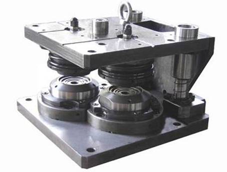
To speak properly we will start by defining the names that each of them receives: See figure 1
Figure 1
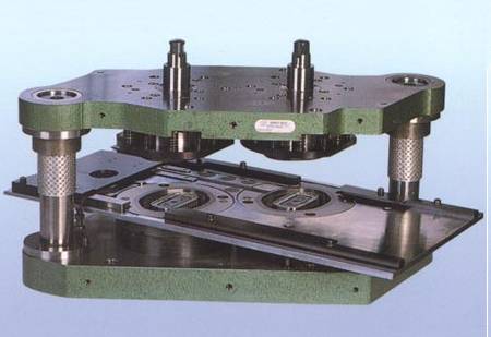
A die consists of two main parts:
- a) The superior, – superior tool – that we will generically call the punch, which is fixed to the car of the press and that goes up and down – in reciprocating movement – following the path – race – of the same in its displacement on the slides of the press.
- b) The bottom, – bottom tool – that we will generically call matrix, fixed on the table of the press. On it is the cutting table or board, on which slides the band of the material to be cut (Tin, aluminum, etc.).
Frequently both parties are linked together by a system of guide columns
Process description:
1 – When the upper tool – or “punch” – descends, the first piece that comes in contact with the material band is a clipping punch, whose lip pushes the band vigorously against a slight flat area on the upper part of the blade. cut, which is housed in the lower tool This action will allow the immobilization of the band facilitating a correct cut. Immediately the punch intervenes making the cutting of a disc by shearing between its edge and that of the blade. See figure 2
2º.- The car of the press continues its descent. The cutting punch pushes in front of it the disc that has just cut and supports it on the presser ring, which starts to descend, driven by the lip of the punch. The stuffing starts from the moment the disc comes in contact with the center of the matrix. See figure 3
FIGURE 3
3rd, – The drawing progresses. The punch block pushes the disc over the inside of the matrix center. The metal slides on the spokes of the center of the matrix, progressively escaping the pressure exerted by the punch lip on the presser ring.
The inclination of both the punch lip and the presser ring facilitates the sliding of the metal.
The pressure exerted by the springs through the spider to the presser ring prevents the formation of creases – wrinkles – on the outer curl of the bottom. See figure 4
4º.- The drawing is finished. The metal has been completely released from the contact between the presser ring and the cutting punch lip. You reach the end of the race, at this time there must be a slight play between the block of the punch and the inside of the center of the matrix that is not indicated in the drawing. On the contrary, there should be a firm blow in the area between the ejector and the matrix center to eliminate the slight wrinkles that could subsist on the bottom crown. Likewise, there must be a blow between the central engraving stamps if the die is equipped with them.
The above conditions are obtained by means of a very precise setting of the bottom dead center of the press carriage. This operation is very delicate because the blow must be achieved without forcing the press to abnormally high stresses when passing through its bottom dead center. Otherwise, there will be excessive fatigue and rapid deterioration of the press and the tooling. See figure 5
FIGURE 5
5º.- After passing through the bottom dead center, the punch elevates it aided by the energy stored by the compression spring during its descent. The bottom fitted in the upper tool goes back with it. In this type of die, it is not necessary to apply vacuum through it as it is practiced in other types of tools; the grip of the bottom between the center of the punch and the inner face of the same cutting punch is sufficient to prevent its premature expulsion. See figure 6
FIGURE 6
6º.- The superior tool reaches the top dead center of the race. The action of a fixed stop on the head of the ejector produces the relative displacement of the latter with respect to the set formed by the cutting punch and the center of the punch.
The ejector advance is going to take off the bottom. Said bottom, when free, will be hit by the ejector that will throw it towards the evacuation channel through which it will be guided to the rizadora. See figure 7
FIGURE 7






0 Comments