SUMMARY
The premature fall of the shell – or sketch of an easy opening ends – from the punch assembly, in a double die, has been an annoying problem for years. The magnitude of this problem has increased significantly with the introduction of shells with a central inverted and deeper panel, such as that used in the covers for beverage containers. The “Shell Control” retains the shell inside the punch using a vacuum generated behind it.
INTRODUCTION
A problem of anticipated shell shedding has persisted for years, to varying degrees, in many standard double dies, used in the production of shallow bottoms with or without an inverted central panel. The magnitude of this problem of shell falls increases significantly, due to the special geometry of the easy opening lid for beverage containers, in them a peripheral groove increases the depth of the tray. Nominally the inverted central panel has the same depth as a deep lid. This special geometry has created a marginal situation, causing frequent drops of shells out of the punch, almost immediately after it is removed from the blade, after forming the shell. The fallen shell is released before it is properly ejected by the ejector of the tool, and gravity does not move it quickly enough, consequently this shell is “chopped” in the next press stroke.
COMMENTS
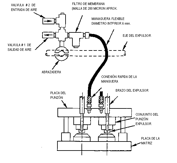
A “Shell Control” was designed to retain the same inside the punch, during its upward stroke, controlling the exhaust and the entry of air into the hermetic cavity of the punch that forms behind the shell. The system is described in Figure No. 1. Thus the shell was dislodged positively only when the punch reached its top dead center, by the action of the ejector ring.
Figure nº 1
To do this, in the case of a double die, a socket is connected to each hermetic cavity, through which the compressed air escapes inside the punch, during the formation of the shell, through the exhaust valve # 1. valve allows flow only in one direction. After the shell is formed, the passage of inlet air into the punch cavity is allowed from the atmosphere through valve # 2, and through the same hose that previously served to expel the air. This valve also allows one-way flow, inverse to that of valve # 1. The air could flow back freely if the restriction of valve # 2 did not prevent it.
It seems that the force of inertia, acting on the shell, tends to keep it fixed to the center of the matrix, after the punch exceeds the lower point of death. See Figure No. 2. This momentary hesitation of the shell on the matrix center during a distance “X”, increases the volume of the cavity on the shell enough for the pressure to be reduced 0.023 Kg / cm2. This vacuum generates a vacuum that exceeds 100 mm Hg (column of mercury) or what is the same 0.023 Bars, this vacuum will suck air into the cavity through valve # 2. A rapid increase in vacuum will also occur when the shell is thrown out of the punch, by the action of the ejector ring, when the car arrives at its top dead center. Therefore to prevent deformation of the shell, it is necessary to take care to limit the vacuum to 100 Hg.
Figure nº 2
Shell productions were being made on MB 314 press at a speed of 240 strokes / mi, with the presence of this problem. The production was reduced to minimize the fall of lids. With the “Shell Control” system described, it was possible to raise the speed of the press to 340 strokes / mi, with full satisfaction.
It is necessary to use an independent “Control” system for each punch of the double punch, because during the intermittent feeding of zigzag cut strips, a punch is exposed to atmospheric pressure during the first and last cut, invalidating the action of the system. The modification of the double die to use this system is relatively simple and its cost is not high. The “Shell Control” does not require special adjustments.







0 Comments