
SUMMARY
Description of a DRD packaging manufacturing line and the equipment that compose it
INTRODUCTION
The manufacture of cans by the DRD technique, is relatively recent, reached its development in the last quarter of the last century. Its designation DRD has its origin in the English words “draw, re-draw”, which perfectly describe what this technique consists of.
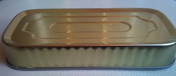
Starting from a flat material, it is planned to carry out a first cutting and drawing operation, generating a cup or sketch of a much larger diameter and lower height than the can that is intended to be obtained. Then, in another new complementary embedding operation, the appropriate diameter and height is reached. . For very tall cans, two re-shake operations may be required. The process ends with the formation of the bottom profile, the cutting of the remaining material on the upper edge, cordoning – if required -, and the corresponding packaging.
We refer to work:
where this technique has been discussed in detail. Now we intend to describe the manufacturing line necessary to put it into practice.
CHARACTERISTICS
These lines allow to work, from materials – tinplate or TFS – of special qualities, with a good saving of raw material and production rate quite high. There are lines from just over 10 cans / minute up to 800 cans / minute or more. These lines are very compact, occupying little space and producing a high quality of packaging.
Its basic characteristics are:
– A very economical material use
– Total synchronization in the sheet metal supply to the header press or sketches and from these to the following operations, by means of a very compact circuit that saves surface in the manufacturing workshop.
– Acceptable noise level, provided it is well soundproof.
– Centralized control system, with central and individual table by machine, always incorporating abnormality detection indicators.
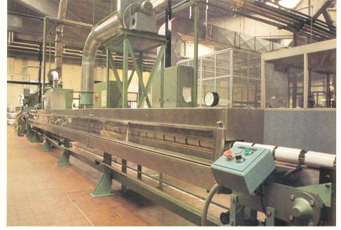
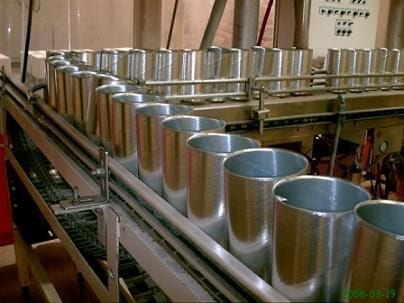
Logically each line can present particular characteristics, depending on the needs of the manufacturer and the type of can to be manufactured. Photo No. 1 presents an overview of a high-speed DRD line.
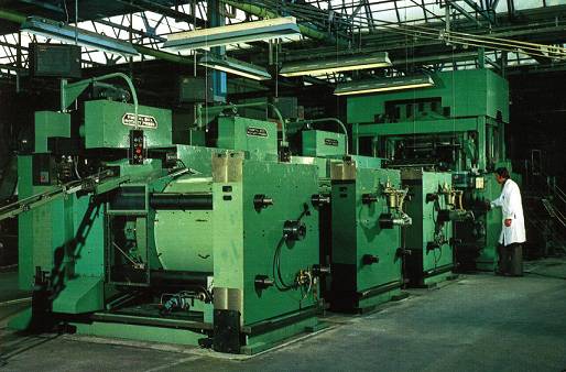
Figure nº 1: View of a DRD line
COMPOSITION
In drawing no. 2 a perspective view of the line of packages of this type indicated in the above photo appears. It is usually formed by the following equipment:
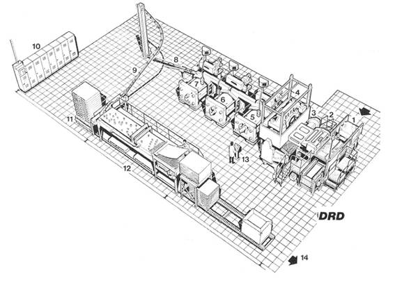
Figure nº 2: DRD line
1.- Conveyor of packages of sheets of material, cut in primary scroll. This material can come already varnished with the suitable systems, capable of supporting the stuffing. It can also be fed directly into coils
2. Lubricator, in which a layer of paraffin and another lubricant is applied on both sides to facilitate the stuffing.
3.- Feeder to the press. It usually has a double movement, frontal and lateral, according to a coordinate system. This way a good surface use of the metal is achieved.
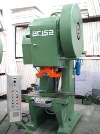
4.- Sketch press or cups. It is a multipunzón press, that cuts and realizes the first operation of stuffing simultaneously. The set works as a simple drawing, forming a sketch or cup of straight walls and flat bottom. See figure no. 3, in it there is the necessary sketch for a round can RO 65 x 70

Figure nº 3: Cup for a DRD can
5th.- Re-embedding press. It can be a press of horizontal configuration, as it is the case that appears in this drawing nº 2, although there are some that work vertically. Embed the outline to the final dimensions of diameter and height, folding the top edge to form the closing flange. Figure 4 shows an example of a refill operation for the aforementioned can.
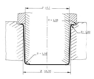
Figure nº 4: Re-embedding operation in a DRD can
6º.- Second press of rembutición. Recalibrates the body of the can to its final dimensions and above all forms the profile of the bottom of it. See drawing nº 5
Figure nº 5: Formation of the bottom profile in a DRD can
7º.- Trimmer. It removes the excess material from the folded upper edge of the can, which has an irregular edge as a result of the stretching and the direction of rolling of the steel. See figure # 6.
Figure nº 6: Cutting of excess material in the flange in a DRD can
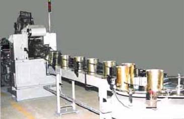
8ª.- Unloading of finished cans
9º.- Can transport systems: Magnetic elevators, falls by gravity, etc.
10º.- General control cabinets of the line.
11º.- Empty wooden pallet feeder.
12º.- Paletizer of cans.
13º.- Command control desk for the line.
14º.- Exit of pallets full of cans towards the warehouses.
After the trimmer – point 7 – add the necessary complementary machines to finish the can such as: cordon, leak tester … They are conventional machines, but transformed to work only on one side of the boat, as the bottom of the can it is incorporated, preventing access at both ends of it.
For low-speed lines, the 1st operation press can be a conventional low-height embossed or bottom-fabricated packaging machine, equipped with a single or double punch. The press 2nd operation, can be a vertical transfer press of 3 stations – re-shaping, bottom formation, trimming – followed by the appropriate complementary equipment.
LINKS
http://www.alfons-haar.de/25.html
 Troubleshooting strategy for an aluminum beverage can production line
 FORMING PROCESSES IN AN ALUMINIUM BEVERAGE CAN PRODUCTION LINE
 DIE FOR ENDS
 INCIDENCE OF A LINE DESIGN IN YOUR PRODUCTIVITY
 LINE FOR BEVERAGE CANS “THREE PIECES”
 LINE FOR PACKAGING “PARTY”
 PACKAGING IN SMALL LINES OF EMBUTITION PACKAGING
 VERTICAL FEEDING IN PRESSES FOR EMBUTITION
 “U” LINE FOR RECTANGULAR ENDS
 PACKAGING TWO PIECES DWI


0 Comments