
INTRODUCTION
Over time, the packaging manufacturing lines have been evolving in an accelerated way, always looking for a fivefold objective:
– 1º.- Improve the technology of the equipment, to increase the quality of the cans
– 2nd.- Increase the production rate, so that more cans can be obtained per unit of time.
– 3º.- Automate the facilities in order to reduce direct labor on the equipment.
– 4th.- Optimize the use of raw materials, to reduce their consumption
– 5th.- Compact the location of machines, to save occupied surface.
All of them had a very important impact on the cost of exploitation, either directly (saving raw materials or direct labor) or indirectly (reduction of rejects due to defective quality or surface of industrial buildings).
In this paper we will focus on the 2nd and 3rd points, that is, the evolution of speed and labor used in a line over time. We will see in the specific case of an installation to manufacture round cans three pieces for preserves. The increase in productivity achieved by the improvement of both factors has been impressive
For them we will put several examples of line design for this product, comparing old with modern, although all of them of possible current employment, depending on their use of the country’s industrial development (labor cost), investment capacities or volume of the market to which it is destined. At the end we will make a summary table that reflects the evolution of productivity, expressed in hours / man per thousand cans (HH% 0 )
LOW SPEED LINES
.- A: Lines of locked or seam
As they were incorporating the primitive machines to the metal industry, which was initially all handcrafted, they were ordered by groups of the same type, for example all the tabs were gathered together, or all the seamers, etc. led by the idea of organizing the manufacturing workshop by skilled labor. This required a large transfer of material in the process of manufacture from one place to another.
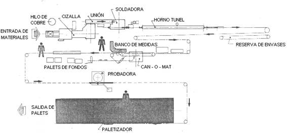
Soon, at the beginning of the 20th century, lines began to be organized, ordering the machines by the sequence of operations of the can being manufactured. The union between them was carried out by means of storage tables or transporters. Thus, in the first part of this century it was common to work with equipment provisions such as the one described in figure 1. It is intended to produce round, agraphed and welded cans, especially of a certain size.
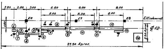
Drawing nº 1: Manual line for round and welded round cans
The line is composed of:
1.- Corners of flat bodies corners
2.- Rolling of bodies, which forms the cylinder. Both machines are operated with only one worker.
3.- Conveyor or ramp by gravity for the transfer of the rolled body
4.- Bigornia press for forming hooks at the ends of the body. Operated by a person
5.- Conveyor belt, with pickling applicator (preparation for tin welding). Requires an operator.
6.- Food or waiting table for bodies
7.- Bigornia press for the engraving of the hooks of the body. Operated by a person
8.- Chain conveyor for the manual application of tin welding by wire, requires two operators.
9.- Manual spanner. An operator
10.-Tape conveyor
11.- Manual closing machine. Two operators, one feeds tapas and another closes
12.- Conveyor belt
13.- Packaging. An operator
14.- Storage platform
The packaging was initially made in paper bags or boxes. Subsequently, direct palletization was implemented.
The approximate space occupied by a line of these characteristics is indicated on the drawing, as well as the necessary gas intakes with black circles and electricity with white circles
The theoretical capacity of production is 1000 cans / hour and the human team required 10 people from direct labor, to which we had to add one more to recover defective cans. Total 11 people. Therefore, 11 HH 0/00 is required . In drawing no. 1 the work stations are represented by semicircles in black and marked with capital letters. The labor necessary to cut the flat bodies from sheets is not taken into account, since as the production capacity of the shears was well above the line, this operation was carried out in the section of shears, where few were sufficient to meet the needs of several lines.
In the drawing nº2 a similar version of this type of lines is presented, in this case it prepares to manufacture agrafted cans but with application of thermoplastic cement in the lateral seam to achieve airtightness. These cans are not processable.
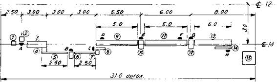
Drawing nº 2: Manual line for rectangular and cemented rectangular cans
In this case the line is composed of:
1.-Feeding table of flat bodies
2.- Cutter of corners of flat bodies.
3.- Thermoplastic cement applicator on a lateral edge of the flat body. This cement is applied in the part corresponding to the outer hook, by the inner house of the can.
4.- Rolling of bodies, which forms the cylinder. These machines are operated with only worker.
6.- Bigornia press for forming hooks at the ends of the body
7.- Tape conveyor
8.- Bigornia press for the engraving of the hooks of the body
9.- Chain conveyor for cement refunds. Operation necessary to eliminate possible fractures, produced during the operation of agrafting, of the applied film of cement. This is achieved by moving the can, lying with the seam up, and subjecting it to the heat of a gas burner positioned above.
10.- Manual spanner
11.-Tape conveyor
12.- Manual seamer
13.- Conveyor belt
14.- Packaging
15.- Storage platform
The same considerations we have made for the first line are applicable in this case. The theoretical capacity of production is also 1000 cans / hour and the necessary personnel is 8 operators plus one of surveillance and recovery of cans, total 9. Therefore consumes 9 HH 0/00.
When the product to be manufactured is a non-round can or closed at both ends, the line gets a little complicated, appearing new machines with: folding, 2nd closing, etc. If these cans are equipped with a handle, neck or other accessory, the number of people can reach 15 or more and production drops to 800 cans / hour, so the labor consumption is approximately 18.5 HH 0/00 . which is a lot .
.- B: Electric welding lines
The appearance on the market – in the middle of the last century – of the technique of spot welding as a means of joining the lateral seam of the bodies of the cans, represented a very important advance in quality and especially in reduction of manpower in the low speed lines. The production in cans / hour did not vary substantially, but the productivity of the installation increased.
In the drawing no. 3 a manual line of this type is presented in plan. In relation to the previous ones, the cutting equipment has disappeared, bigornia presses for the locked or seam and means to weld it.
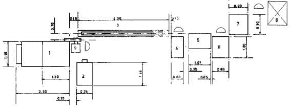
Drawing nº 3: Manual line for electrically welded round cans
It is formed by the following machines:
1: Welding machine for the side seam.
2: Manual winding of bodies, which forms the cylinder.
3: Chain conveyor.
4: Manual spanner
5: Accumulation table
6: Semiautomatic seamer, equipped with turret for feeding tapas. Just one person to feed and remove the can.
7: Packing table
8: Storage platform
The theoretical capacity of production is 1000 cans / hour and the necessary personnel is 4 workers plus one support and surveillance, total 5. Therefore it consumes 5 HH 0 / 00. That is to say, the direct productivity has at least doubled in relation to to the lines of locked or seam. In addition, the welding machine is equipped with a semiautomatic device for rolling up bodies, – position 9 of drawing no. 3 – it can be reduced by one more person. Therefore, with the reasonable investment in a welding machine and a lid feeder for the seamer, keeping the rest of the machines, the improvement is evident.
HIGH SPEED LINES
.- A: Lines of locked or seam
Almost simultaneously to the low speed lines, others began to be used with higher cadence for those formats that presented high consumption in the market. This high rate was achieved with automatic equipment, which required little labor, linked together by elevators, falls by gravity and / or conveyors. An example of automatic line, already in operation in the first half of the twentieth century, is that indicated in drawing No. 4. For more than 60 years these lines were in use, although they were progressively improved as a team and in benefits, especially in speed. Initially they worked at a rate of 60 to 100 cans / mi and at the end of this stage they exceeded 450 cans / ml.
The one presented in figure 4 could work at 300 cans / ml. The joints between machines are made by means of levators and falls by gravity. These last ones were replaced in more modern lines by overhead cable transporters.
Drawing nº4: Automatic line of locked or seam
Essentially they were formed by:
1.- Automatic double shear
2.- Automatic forming of engraved bodies
3.- Seam welding machine with tin-lead alloy
4.- Automatic flap
5.- Automatic closing machine
6.- Packaging.
Initially it was made in cardboard boxes or paper bags, which consumed a significant amount of labor, even having semi-automatic box fillers. Subsequently, I evolved to direct palletization, which meant a significant saving of the same
In the installation of drawing no. 4, there is no testing machine, although in many cases it was used, it used to be of the “double wheel” type, although its efficiency was limited. Subsequently, other machines were incorporated such as cordons. Both one and the other did not require direct labor.
A typical line of the “twenties” worked at 120 cans / ml and needed 7 people, distributed as follows: a machining, a shearing and forming operator, a seamer operator, four operators in the packing area including the handling of boxes or bags. In these conditions the direct labor consumption was 0.97 HH 0/00
.- B: Electric welding lines
At present the most modern lines of this type have increased their speed, and even more has been able to reduce their direct labor thanks to the use of the following equipment:
– Automatic connection between shear and welder.
– Automated warehouse of large capacity caps in the seamer
– Automatic palletizing of cans
– Grouping of several machines in a single set (“can-o-mat”)
– “U” layout of the machines.
All this despite having incorporated new operations such as welding varnish and reducing the ends of the body.
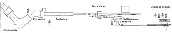
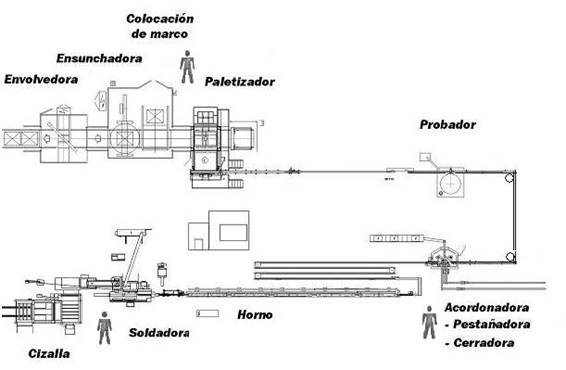
Drawing No. 5 presents an example of this type of lines. The name of each machine is indicated on it.
Drawing nº 5: Modern automatic line for round cans three pieces
These facilities can reach a speed of 800 cans / mi and even more. Your need for direct labor is limited to: One line mechanic, one general operator, and another in the package. In this case, therefore, the direct labor consumption is 0.02 HH 0/00
Of this type of line there are many variants in the market, linked to their use. For example another case is that presented in drawing No. 6 which is an application of this criterion for the manufacture of aerosol cans.
Drawing no. 6: Modern automatic line for electrically welded aerosol cans
The following table is a summary of what has been said in terms of productivity values of the different types of lines, always thinking of “three pieces” type packaging.
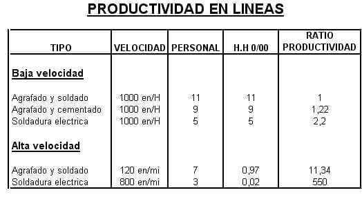
Specifically, the initial productivity of a line has been multiplied by approximately 550.
This study does not consider the incidence of indirect labor in the facilities, which includes, among others: internal logistics (forklifts), warehouses, quality control, maintenance, etc. Advances in this field have also been important with the use of automated warehouses, automatic control equipment, specialization of mechanos, etc.
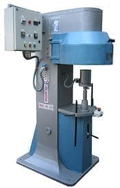
 ROTATIVE MACHINE TO INSERT CANS
 MANUAL DEPALLETIZER OF PACKAGING
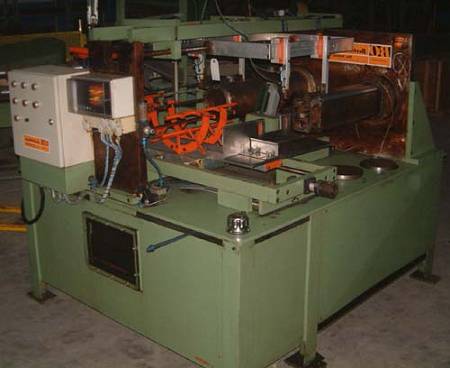
 FEEDER TO AUTOMATE A MANUAL SEAMER
 MANUFACTURE OF SHAPED PACKAGING BODIES
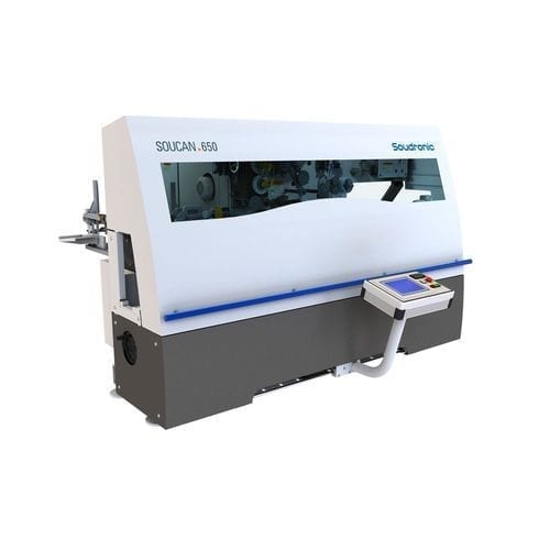 WELDING IMPROVEMENTS
 LINE FOR BEVERAGE CANS “THREE PIECES”
 PACKAGING IN SMALL LINES OF EMBUTITION PACKAGING
 CAN LINE “TWO PIECES DRD”
 “U” LINE FOR RECTANGULAR ENDS


0 Comments