
INTRODUCTION
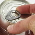
A In the metalworking industry, the purchase or exchange of ready-made components (phons, easy-open caps, aerosol domes, etc.) is a common occurrence. This can occur between packaging manufacturers, as some of them specialize in components, or between metallographers and packagers. For these cases, and also simply in the normal supply of cans with their loose caps to the filling industries, it is sometimes good to set up a quality control system for these already manufactured components.
We now intend to go a little deeper into the specific topic of monitoring the dimensional quality of caps/bottoms. What is described here is also valid for the direct installation of a control system in the production shop of a metalworking plant.
We will not go into the definition of defects, sampling plan, quality levels, etc. We will focus on the parameters that can be controlled through concrete measurements, providing the means to make these measurements as simple as possible.
Nowadays there are very sophisticated means of control, which allow to measure automatically the main elevations of a bottom. Due to the high cost of this equipment, it is only justified when the volume of work is large. This makes their acquisition difficult for small companies. The procedures explained here use simple and inexpensive instruments and are designed for the latter type of companies.
PARAMETERS TO BE CONTROLLED
We will break down which are the basic measures of a fund that must be controlled. To do so, we will refer to Figure 1 below.
Figure 1
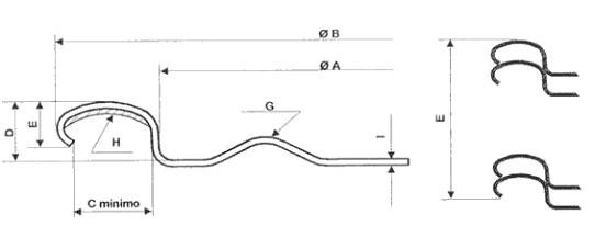
THE FOLLOWING TABLE SUMMARIZES:
a) the dimensions to be taken – marked with the same letter as in the figure -, b) the concept they reflect and c) the normal tolerance applied in these measurements.
For tinplate thickness and hardening, we refer to the international standards in force. The channel width has no tolerances, the control gauge marks its minimum value. The profile of the bottom panel shall be as agreed between the parties.
DIMENSION CONCEPT TOLERANCES
- Tinplate thickness According to standards
- Tinplate hardness According to standards
A Trough diameter +- 0.05 mm.
B Outside diameter +- 0.20 mm.
C Minimum channel width –
D Trough depth +- 0.15 mm
E Number of covers in 2″ (50.8mm) +- 2 units
G Panel profile –
– Composite weight +- 18.5 %.
There are other parameters that can be measured, but we do not include them in this paper because they are either more complicated
– Trough wall radius. Although it is important that it is in correct measurements, its exact verification requires complex means. If the manufacturing die of the bottoms is well maintained, it should not show variations.
Let’s consider that we already have a complete table with the values of the parameters to be controlled. It can be made up as above, adding in the column of tolerances the amounts of each dimension. With it in front of us we can start the control.
THICKNESS
Purpose: To ensure that the bottom has adequate mechanical strength.
Measuring instrument: Micrometer with thin or semi-spherical tips, preferably digital.
Method: Direct reading.
HARDNESS
Purpose: To ensure that the bottom has adequate mechanical strength.
Measuring equipment: Hardness tester equipped with Rockwell HR 15T and HR 30T scales.
Method: See equipment manual in each case.
BOWL DIAMETER “A”
Purpose: To check that the mandrel will fit correctly on the bottom during closing.
Measuring instrument: Go/no-go gauge for bowl diameter (mandrel fit) according to drawing Figure No. 2:
Figure No. 2
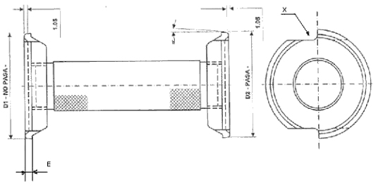
This caliper consists of two chuck-like plates of different diameters. Each one of them has two opposite “X” recesses, which allow checking if it is correctly positioned on the base of the cover pan. To calculate its dimensions, start from the values of the corresponding closing mandrel – see figure nº 3 – and apply the following formulas
Figure 3
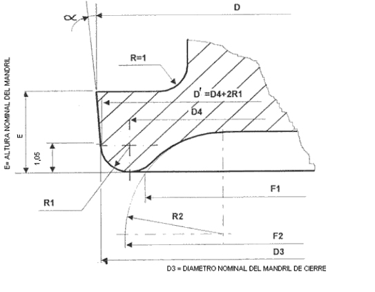
D1 (diameter “no pass”) = D3 (nominal mandrel diameter) + 0.03 mm.
D2 (diameter “pass”) = D3 (nominal mandrel diameter) – 0.12 mm.
The tolerance of the diameters D1 and D2 is -0 +0.02.
The rest of the measurements of the two chucks of the caliper are the same as those of the mandrel. Even a worn mandrel could be recovered to prepare the “raisin” chuck.
Method:
– Caliper “does not pass”: Check if the cover is too large. On a flat, horizontal surface, place the caliper on the cover tray, inclined at 90º in the area of the recesses. Place the caliper completely on the cuvette with light pressure, then check – through the recess – that the radius of the caliper is correctly resting on the radius of the cuvette of the lid. Lift the same in vertical position, if the lid is too large.
– Caliper “pass”: Determines if the cap is too small. Position the caliper in the same manner as above. Lift the same in vertical position, if the cap falls it is acceptable, if it rises with the caliper it is too small.
OUTER DIAMETER “B”
Purpose: To prevent possible problems in bottom feeding. If the outside diameter of the bottoms is outside the measurements, it can lead to blockages in the feeder, guides, stars, etc.
Measuring instrument: “Go/no-go” caliper of the outside diameter of the bottom. See figure nº 4:
Figure nº 4
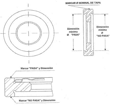
The same has two housings of slightly larger diameters and fear than the outside of the cover. The formulas to determine its value are:
Maximum diameter “pass” = Outer diameter of cover “B” + 0.21 / Tolerance -0 +0.02.
Minimum diameter “no pass” = Outer diameter of cover “B” -0.21/ Tolerance -0.02 +0.
Method: Present the inverted bottoms on each of the two “pass”, “fail” sides of the caliper. The bottoms should not enter the housing on the “not pass” side, but on the “pass” side.
Alternative method: Direct measurement by means of a caliper gauge.
MINIMUM WIDTH OF CHANNEL “C”
Purpose: To ensure that, during the closing operation, the body flange is well seated inside the flange of the cover, without interfering with the curl of the cover.
Measuring instrument: Minimum carcass width gauge according to Figure 5
Figure 5

Method:
– Insert the caliper vertically between the curl and the wall of the cover pan as shown in Figure 5.
– The channel width should be large enough to allow the caliper to move freely around the perimeter of the bottom.
Alternative method: Direct measurement by means of a caliper gauge.
BOWL DEPTH “D”
Purpose:
a. That the closure mandrel will adequately penetrate the lid.
b. That the capacity of the container will be as intended.
Measuring instrument: Obtain from the market or prepare a caliper as shown in Figure No. 6.
Figure nº 6
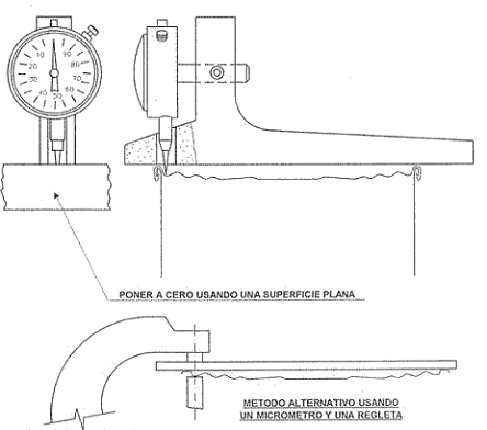
Method:
– Set the dial indicator to zero on a flat surface.
– Check that when the caliper is removed from the flat surface, the stylus has a travel that allows it to reach a value greater than the cuvette depth to be measured.
– Place the base or support rule of the caliper on the bottom flange, trying to position it diametrically and with the probe in contact with the base of the cuvette area.
– Move the caliper slightly until you find the point of maximum reading on the dial. At this point we will have the desired measurement.
The stylus should have a fine point and be long enough. To ensure that the bottom to be measured is in a stable and firm position, it is advisable to support it on a flanged body of the same diameter.
Alternative method: Measurement with a micrometer and the aid of a strip, as shown in Figure No. 6. The thickness of the strip and the thickness of the tinplate must be deducted from the reading.
NUMBER OF COVERS IN 2 INCHES (50.8 mm) “E”
Purpose: To indirectly determine that the height of curl of the covers is as specified. This ensures a smooth movement of the bottoms through the closer and a proper seal.
Measuring instrument: Caliper for checking the number of caps in 50.8 mm, according to figure 7.
Figure nº 7
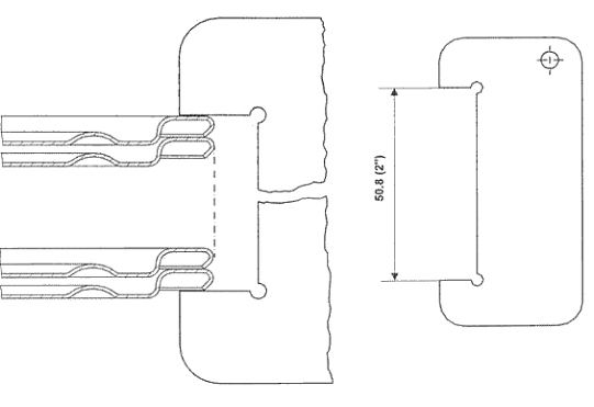
Method:
– Insert a sufficient number of caps to fill, without pressure or slack, the slot of the caliper.
– Count the number of bottoms that fit.
Alternative method: Set a caliper to 50.8 mm and use it as a caliper.
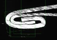
BOTTOM PANEL PROFILE “G”
Purpose: To ensure proper bottom performance during container use.
Measuring instrument: Visual.
Method: Direct observation.
WEIGHT OF COMPOUND
Purpose: To verify that the weight of compound contained in the bottom flange is as specified. The compound plays an important role in ensuring the tightness of the seal, therefore its presence in the right quantity is essential.
Measuring equipment: Laboratory balance with mgrs accuracy.
Heat proof container.
Heat source.
Thermometer (from 0 to 100 ºC).
Method:
– Principle: Weighing difference of a background with and without compound.
– Sample: Four backgrounds taken at random.
– Reagent: 50% solution of 96º alcohol in water.
– Sequence:
- Number the bottoms and weigh them one by one.
- Immerse them in the reagent for about 2 to 3 minutes, keeping the bath warm, approx. 90ºC.
- Rub the compound until it comes off, taking care not to damage the interior varnish.
- For complete removal of the compound, it may be necessary to lay the flange flat, using pliers, and repeat the operation.
- Re-weigh the bottoms, one by one.
- Determine the weight of compound that each had by difference
- Calculate the arithmetic mean of the four readings.
COMMENTS
Although in some tests an alternative method, by direct measurement, is indicated, it is better to use the calipers, for the following advantages:
– To have a constant criterion and eliminate the possibility of error in the measurement.
– Ease of implementation. Very simple training of personnel.
 Analysis, coatings and physical properties of the lids
 Manufacturing Process for Easy-Open Lids
 DIMENSIONS OF SEFEL FASTENERS
 How do I disassemble the double seal for analysis?
 HOMOLOGATION OF LIDS DUE TO CHANGES IN ANY OF THEIR SPECIFICATIONS
Canning lids
HOMOLOGATION OF LIDS DUE TO CHANGES IN ANY OF THEIR SPECIFICATIONS
Canning lids
 ELEMENTS OF THE DOUBLE SEAL
 DIMENSIONAL CONTROL OF THREE PIECES TYPE PACKAGING
 QUALITY CONTROL VALVE ROLL AEROSOL COVES