
SUMMARY
Information for the construction of chimney caps in metal installations.
UTILIZATION
The cap is a piece that ends the end of a gas pipe or chimney. It is always located outside, on the roof of the industrial installation and can have different functions, among others:
– Facilitate the access of air from outside.
– Allow the exit to the outside of gases generated in the industrial process.
– Prevent the entry of rain, hail or other atmospheric agents into the industrial installation.
– Prevent the introduction of foreign elements in the conduit that protect, such as leaves, plastics, papers, birds, etc. that hinder driving.
It receives this name because of the similarity it presents to a small hat, which covers the head or end of a vertical gas conduction.
Its internal shape and design is related to the function it performs in the installation. In the case of the metal industry its use is frequent and is almost always associated with points where a combustion or application of heat is generated with the release of volatiles. Specifically, it is used in:
– Polymerization furnaces in sheets varnishing lines.
– Ink drying ovens in lines lithographed leaves.
– Polymerization furnaces of rubber gaskets on capsules and bottoms.
– Polymerization furnaces of side welding protection varnishes.
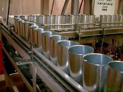
– Lines for the manufacture of two-piece containers for beverages.
– Etc.
The construction of these hoods is entrusted to houses specializing in gas pipes, but the order of the same is not always justified, either because there are no signatures of this type in the vicinity, either because of the scarce workload or because of the simple economy. Therefore it is sometimes the same metal company that can run with the design and construction of them. Therefore we present in this work how to define, based on its use, the characteristics of a cap for this industry.
SUCTION HAT
It is used for the intake of air from outside. A typical case of this use is in the final part of the tunnel kilns, used in the lines of varnishing and printing of packages of flat laminates.
In this area, it is necessary to apply a lot of fresh air from the outside, to cool the sheets before being stacked, once the polymerization and drying phase of the varnishes and inks has finished. This air is taken from the atmosphere by means of powerful fans. Until they get the air from the outside through pipes that start on the roof of the lithography ship. These tubes must be protected by caps that allow this intake, known as “aspiration” type. The drawing No. 1 presents a section in elevation of an overflow of these characteristics.
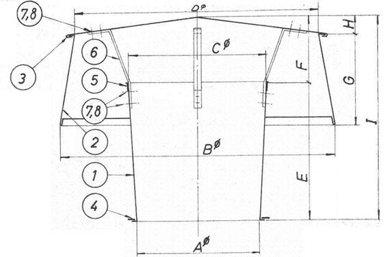
Figure No. 1: Suction head
Its purpose is to cover the mouth of the chimney, letting through an orifice, in the form of a circular crown and positioned at its base, the atmospheric air.
It consists of an envelope 1, extension of the chimney, a cover 3, which covers the whole and a skirt or shield 2, which protects laterally. All structured on a frame.
The caps are made of galvanized sheet and steel plates or profiles. In table 2, each of the pieces of the suction cap of figure 1 is listed, indicating the quantity, denomination, material or observations necessary for each component.

Table nº 2: Materials for suction cap.
The dimensions of a cap are determined by the diameter of the pipe it protects. For the case that we are commenting on lithography ovens, the diameter of these conduits is usually always greater than 500 mm. As a practical example of dimensioning for different chimney diameters, we include table No. 3, where several are grouped.
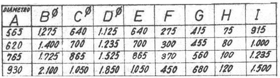
Table nº 3: Measures of suction hoods according to the diameter of the chimney
The caps are mounted by means of flanges screwed to the end of the conduit.
EXPULSION SOMBRETTE
Sometimes it is necessary to send to the atmosphere fluids generated during the process and that do not harm the environment. It can be hot air, steam, etc. A normal example in a packaging factory, is the hot air produced in the cooling of the sheets of flat laminates at the exit of the ovens of the lithography section.
The cold air introduced from the outside, once it has been passed through the leaves in the final section of the oven, has been heated and must be evacuated from the ship so as not to overheat it. It uses extractors that raise it up the chimney to the outside. In cold areas or in winter, this air can be used as a heating element in the building.
The caps that finish off the exhaust ducts of this air must allow its evacuation, while protecting the chimney from inclement weather and foreign elements. In figure 4 a section in elevation of a type of ejection cap is drawn. Its shape is of two trunks of cone in opposite position one from another, united by a cylinder.

Figure no. 4: Air ejection liner
In its center there is a rain collector funnel with lateral outlet. Both this funnel and the outer cone trunks are mounted on a lower cylinder that connects to the exit chimney. Said funnel is of greater diameter than the mouth of the chimney, and is coupled on it at a certain height thereof, in this way it facilitates the flow of gases towards the outside, since it presents an exit thereof in a gently inclined form and cancel.
For the elimination of rain that is not collected by the funnel, a separation is maintained between the lower cone trunk and the connecting cylinder with the chimney, by means of spacers (no. 6 in the drawing), through which it drains the water that flows through the interior walls of the cap.
The same as the suction hoods, this type is also usually made of galvanized sheet, but if the circulating fluids contain a lot of water vapor, as it can be the case of drying ovens of water-based varnishes, it is suitable to make them in steel stainless. Table No. 5 details the quantity, denomination and material of the components of this cap, although the sheet is not included, which must have a thickness of 1 mm.
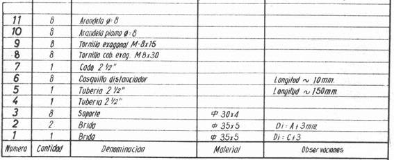
Table nº 5: Materials for ejection cap.
Also as in the first case, we include a table with the dimensions of this type of cap for different chimney diameters. Due to their diversity of uses, their diameters can vary greatly, although in the metal industry they rarely exceed the value of 1000 mm. See table nº 6.
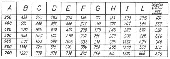
Table nº 6: Measures of ejection hoods depending on the diameter of the chimney
Its mounting on the chimney is also by means of flanges. See detail K of drawing nº 4.
INSTALLATION
For an adequate installation of chimney outlets, equipped with different types of hoods, the following recommendations should be taken into account:
– If an obstacle has to be overcome along the route of the conduction, such as trusses or skylights, of the structure of the roof of the nave, it should be resorted to soft elbows that do not hinder the circulation of the fluids.
– The chimneys should be raised as much as possible on the roof, everything that allows anchoring safety, to improve the evacuation draft.
– If, due to the imperatives of the equipment, an outside air intake and a gas outlet are very close, a certain distance must be distanced between them, by means of elbows installed along the chimneys. This reduces the possibility of returning to the ship, through the suction cap, of fluids dislodged by the ejection cap.
– Including the previous possibility, in case of proximity of exits and entrances, the expulsion of hot air must always be at a higher level than the intake of cold air. Thus the hot gases, which tend to rise, will move away from the intake of cold air, which is still lower, reducing the likelihood of recirculation.
A practical example of an installation in which all these suggestions have been taken into account, is reflected in drawing no. 7.
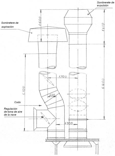
Figure nº 7: Installation of caps.
In the assembly reflected in this drawing, it appears the possibility of regulating the intake and exit of air, taking part of the interior of the ship, by means of a “T” with valve inserted in the chimney.
 FEEDER OF CAPS TWIST-OFF
 ROTATIVE MACHINE TO INSERT CANS
 MANUAL DEPALLETIZER OF PACKAGING
 PACKAGING IN SMALL LINES OF EMBUTITION PACKAGING
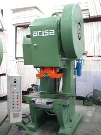 VERTICAL FEEDING IN PRESSES FOR EMBUTITION
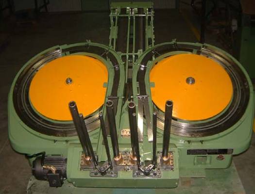 CURLERS
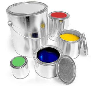 TOOLS FOR PLUGS Paint containers
 TOOLS FOR RING LID Paint containers
 PACKAGING OF COVERS AND ENDS
 CURLING FUNDS ON STICKER


0 Comments