INTRODUCTION CONTAINERS WITH LITHOGRAPHED BODY
Alternatives and evolution of the lithographic reserves in the bodies of the containers
The external presentation of a boat is fundamental for its commercialization. Since its inception, the metal industry has resorted to decorating the bodies – later the lid – of the containers. For this he has gone to different media, paper labeling, lithographed on metal, sheathed with retractable …
Of all these systems, the one that gives an image of better quality and beauty, is the printing on metal. The brightness and tonalities that can be achieved with this procedure are difficult to match by others. However, it has always presented a weak point, this is the presence of some areas without printing contiguous to the welding of the body in the case of three-piece containers, which are the most widely used. This limitation is not presented by the sausages in any of their current manufacturing techniques: simple stuffing, sausage-re-embedding, stuffing-stretching …, but they present others such as their design restrictions, use of weft, etc.
For this reason, focusing on the three-piece packaging, it has long been the desire to eliminate or reduce to the maximum the presence of these reserved areas – henceforth we will designate them with lithography reserves – in order to improve the presence of them.
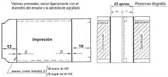
The usual technique used to make the side seam of a boat, during the past, consisted of etching and welding it with a 2/98 alloy of tin and lead. This alloy was applied by means of a rotating roller of a certain diameter that impregnated the agrarian seam. This entailed leaving important lithography reserves in the area. The resulting effect was not very decorative. On the technique of agrafado the work can be seen:
In drawing no. 1 a flat body is shown on the left, already blunt, lithographed externally with the necessary reserves to be able to weld later. To the right he sees the body already recorded and soldier, showing the resulting reserves.
Drawing nº 1: Left flat template of a body with external reserves of lithography. On the right this body with its reserves once agrafado and soldier
The reserves contained here represent an intermediate value and vary depending on the diameter of the container, so for small diameters they are somewhat smaller and larger for larger diameters. The difference is caused by the greater or lesser curvature of the container, which increases or reduces the area exposed to contact with the applicator roll of the alloy.
In order to improve its image, three possible alternatives were used over time:
– Cement the side seam instead of welding it.
– Use lithographic systems resistant to high temperatures.
– Use electric welding that considerably reduced reserves.
Let’s see these solutions;
CEMENTED PACKAGING
This first solution replaced solder tin-lead alloy by the application of a resin or thermoplastic cement. To know more about this material you can see the work:
This cement is applied fused to the inside of one of the engraving hooks. Therefore, this system does not interfere at all with the external lithography of the body, and allows to dedicate to it the whole of its external face Once made the agrafado it is necessary to apply heat to the seam to eliminate possible fractures in the strip of cement , recasting the same, but this heat is soft and does not affect the lithography since the fusion of this resin occurs at about 130 / 140º C.
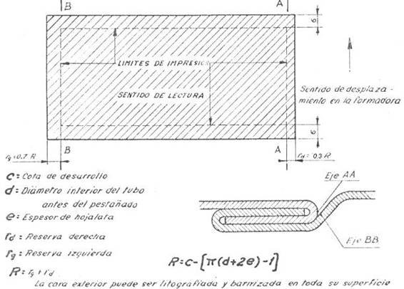
In drawing no. 2, a flat body can be seen for a cemented container with all its printed surface (scratched area). Logically, it is necessary to keep certain areas free of texts to avoid them disappearing when making the agrafado or the closing of the ends. These limits are marked by dashed lines in drawing # 2. The meaning of each dimension and the formula that links them are also explained.
Drawing no. 2: Template for cutting bodies in cement-bound containers, complete printing, limit of texts according to dimensions
Measure R indicates the measure to be discounted at the development level and that must be free of texts.
The image presented by the cemented containers is very pleasant and had a very wide use at the time. However, because they are not processable, because they would lose the sealing in the fusion seam of cement, they can only contain products that do not need to be sterilized, even though their possibilities are many, such as paint containers, varnishes, greases, industrial products , vegetable and mineral oils, etc. In the present they have been partly replaced by electrically welded seam packs, which provide a saving in metal and a higher production speed.
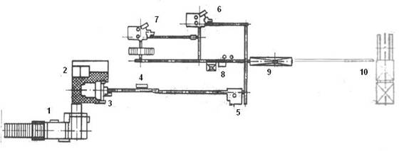
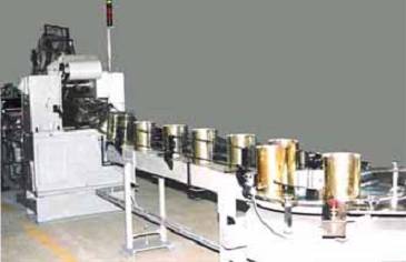
Figure 3 shows the plant of an automatic line for the manufacture of rectangular and cemented containers with the bottom and lid placed and equipped with welded neck or pouring spout. This line works at 60 in / mi with a crew of 4 operators plus 1 mechanic or manager.
Drawing nº 3: Automatic line for rectangular and cemented low velocity containers with closed lid / bottom and equipped to place neck and handle
The main elements of this line are:
1.- Automatic double shear
2.- Clamping presses of bodies
3.- Formadora (agrafadora)
4.- Burners for re-melting
5.- Spanner
6.- Fund Sealer
7.- Capping machine
8.- Installation of neck-spout
9.- Battery burners for welded neck
10.- Palletizer
SOLDIED PACKS LEAVED
The sector looked for viable solutions that allowed to use containers without reserves of lithography for processed products. An alternative was found in overlapping sewing containers.
The overlap technique consists of the superposition of one edge of the development of the body on the other, welding them together, and gives rise to the lateral seam of the overlapped type . Different welding means are used to fix the overlap. In the oldest system, a tin alloy ribbon is inserted between both edges and heat is applied; the fusion of the same welds the whole. The magnitude of the superposition is of the order of 6 mm. Subsequently, electric welding was used to join this overlap, significantly reducing the magnitude thereof, as we will see later.
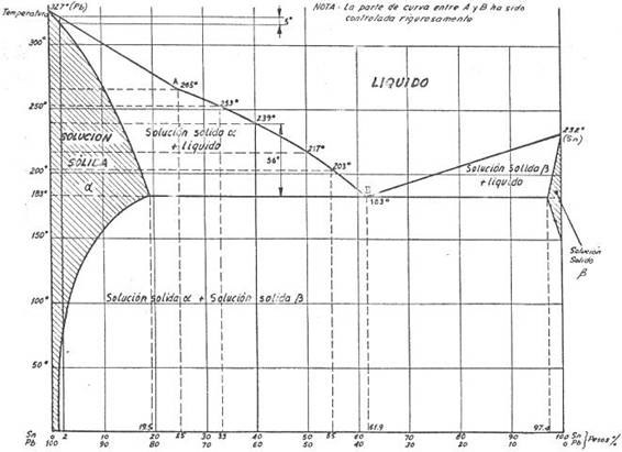
It was the overlap by welding of tin tape that allowed finding a solution to the almost elimination of the lithography reserve. The tin alloy has a low melting point, in particular 183 ° C that of a 62/38 percentage of tin / lead and 232 ° C pure tin. See graphic nº 4
Drawing nº 4: Tin-lead alloy solidification diagram
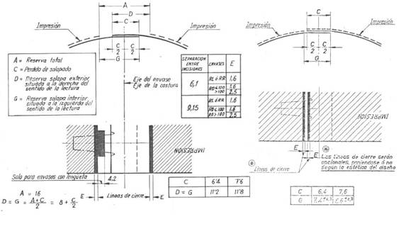
Using high temperature printing systems it is possible to reach these values (183º C) without affecting the lithography. Therefore, it is possible to leave no reserve on the outside of the overlapping side seam, applying heat for the fusion of the alloy through the lithography of the area. Thus, at the end of the process, the package presents a printed outline, except for a narrow strip of 1 mm. In drawing no. 5 you can see: on the left the plant and section of a normal overlapping seam with its corresponding reserves, with an area without printing of 16 mm (level A ) and on the left the version without external reserve on the upper edge , which is the case we are dealing with. In the latter the uncovered strip is G – C = 1 mm.
Drawing nº5: Comparison in an overlapping packaging between normal lithography reserves (left) and “without apparent reserves” on the right
The success of this procedure lies in the quality of many and varnishes used, which we insist must be of the “high temperature” type. The result of this system of work was very positive, but the legal restrictions to the use of tin / lead alloy reduced its possibilities of use. However, it must be taken into account that pure tin can be used as it does not affect health.
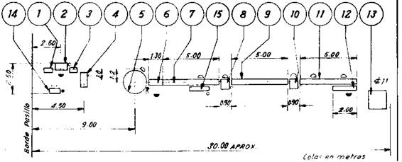
The welders used to overlap the seam by means of tin tape had a profuse use about 30 to 50 years ago, after its use declined due to its low production speed. They are equipped with a series of arms or stations that rotate horizontally; In each station a certain action is carried out as: feeding the body, feeding the welding tape, applying heat (several stations), cooling and ejection. Manufacturers like: Lubin, Somme, Amorosa, etc. They provided a variety of models. In drawing no. 6, the plane of location of a very simple manual line, equipped with a welding machine of this type, is presented in plan.
Drawing nº 6: Manual line for overlapping round containers
The line is formed by the following elements:
1.- Material cut
2.- Cutter
3.- Intermediate table 10.- Manual seamer
4.- Roller
5.-Circular welder by lap
6.- Drop
7.-Cooling conveyor
8.- Manual spanner
9.- Transportator
10.- Manual seamer
11.- Conveyor
12.- Packing
13.- Palet of packaging
14.- Recovery bank
15.- Turbo blower for cooling
This line works at 1000 in / hour with a staff of 10 people. Of course it is possible to automate most operations, increasing speed and reducing labor to less than half. There are lines over 60 in / mi with a direct workforce of 3 people.
ELECTRICALLY SOLDIED PACKAGING
The solution that has prevailed is that of an overlapping seam, with a minimal overlap of edges, but electrically welded. This is achieved packaging for all types of applications, both procedural and not, and with a very small reserves of lithography.
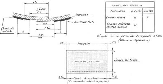
We will not go into the detail of this technique because it is abundantly treated in many other works of this Web. Regarding the application of the impression on the body, we refer to drawing # 7. In it, in the upper left part, we see a detail of the section of a seam of this type where the final lithography reserve is only 4.2 mm To achieve this result it is necessary to leave some lithographic reserves in plane, both of ink and varnish, as indicated in the lower part of the drawing (2.5 mm for inks and 3 mm for varnish).
Drawing nº 7: Limits of printing, varnish and text in lithography for electrically welded packaging
In the upper right part of the drawing, a box appears with the limits of the text limits to be respected, depending on the type of container and its diameter, so that these texts are not affected by the different manufacturing operations.
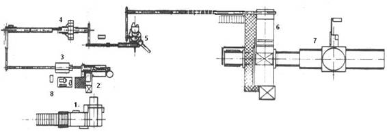
This procedure is applicable to both round and rectangular base packages or any other geometric shape. In the case of a cylindrical can, the lithographic reserves are placed in a random generatrix. In the cans of non-cylindrical shape, is made to coincide with one of the corners of the same. The most usual are rectangular ones. In drawing no. 8, a manufacturing line of rectangular cans with a single closed bottom, which works with this type of reserves, is presented in plan.
Drawing nº 8: Automatic line for welded rectangular containers of half speed
The basic machines of this line are:
1.- Automatic double shear
2.- Electric welding machine
3.- Expander for rectangular
4.- Tab for rectangular
5.- Cerradora for rectangular bottoms
6.- Automatic palletizer
7.- Baler with stretch film
8.- Bank of quality control
Work with 4 people at a cadence of about 80 in / mi
As a summary of the situation, it can be said that currently, except for inlaid containers, it is necessary to maintain a small lithographic reserve in the body of the boat, with the only exception of non-processable containers. In the latter you can opt for a cemented seam without reservations.


0 Comments