
It is important to reproduce the customer’s requirements as accurately as possible, both in terms of color and the quality of definition that plate manufacturers have established. The volume of inks conveyed and the size of the screens used are critical to creating the desired effect. These effects can be radically altered by an incorrect configuration.
For any label using halftones or screens, the following criteria must be guaranteed by specific checks to ensure that the label is accurately reproduced.
1. PRESSURE
1. The printing pressure should be minimal. Adjust the pressure until the image is lost, and then increase the pressure in small increments to obtain a complete image on the blanket.
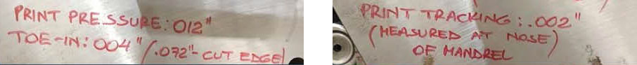
2. The pressure of the printing roller should be minimal. Check with a light source between the print roller being checked and the image on the printing plate. The roller should be parallel to the plate cylinder and have only enough pressure to transfer the ink. A stripe check would yield between 1/8″ and 3/16″ (3mm – 5mm) of parallel line on the plate image.
- The volume of ink supplied through the inking unit must match the color standard precisely.
- The ink used for halftone and screen printing should be as stiff as possible to prevent the printing plate from filling.
All of the above checks are standard for any type of printing. This is the way the machine should be configured at all times.
When a halftone job is in the program, make sure that these checks are carried out before the label change. When changing labels, place each color individually and set it to the color standard as usual. When all the setup is complete, the resulting job will give the best possible result for the customer and should work without the need to clean plates, etc., because of the filler.
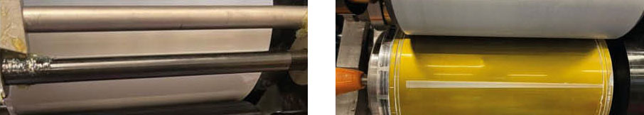
2. ADJUSTMENT OF THE FORM ROLLER
These adjustments are made on the understanding that the inker has been correctly mounted. That the printing rollers are of the correct material for the inks and solvents used, and that the printing rollers are of the correct material for the inks and solvents used, that the printing rollers are of the correct diameter, parallel and mounted on the machine using the pins by location
Two types of print roller launch mechanisms are available. The first is the CMP in which the ejector cam operates with a wedge and a tie rod. The later model is that of the CD2 machine, in which the cam acts against a pair of round conical wedges. The mechanism and roller diameters are different, but the actual setting requirements are identical.
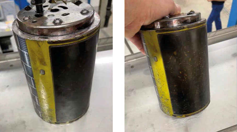
For ease of fit, a dummy cylinder can be fabricated from aluminum that fits the plate cylinder shaft and has an outside diameter of 5,000″. This is equal to the diameter of the image surface of the printing plate when fitted to a magnetic cylinder.
Shape roller adjustment.
- Move the rollers as follows
- Place a full-image printing plate in the inking unit to be adjusted.
- Starting with the small form roller, rotate it clockwise away from the plate cylinder and towards the lower oscillator.
- Position the roller parallel to the lower oscillator using the brass eccentric.
- Adjust the pressure of the laminating roller so that it touches the oscillator and lock it with the knurled locking ring.
- Adjust the large form roller in the same manner, but turn it counterclockwise away from the plate cylinder.
- Trigger the form rollers
- Adjust the small roller parallel to the printing plate image (with a slight even gap) using the tensioner on CMP or the cone on CD2.
- Adjust the pressure of the small roller so that it touches the surface of the printing plate.
- Adjust the large form roller parallel to the image on the printing plate.
- Adjust the roller pressure so that it barely touches the image surface of the printing plate.
- With the printing plate clean and the machine stopped, feed the printing rollers in and out. There should be two parallel lines of ink on the printing plate. For the large roller this should be approximately 5mm and for the small roller approximately 3mm.
- If you want to register these settings, place a piece of white paper between the roller and the printing plate image, and run a path in and out.
ASSESSMENT AND ANALYSIS OF RESULTS
There are a number of quick checks that indicate whether the form rollers are set correctly or need to be readjusted. They are as follows:
When changing labels, observe the printing plates when removing them. After a long print run, some ink leakage in the non-image area of the printing plate is to be expected. If it is opaque in appearance, the ink will peel off. If there is any sign of spreading or glossiness, it is due to the pressure of the print roller.
If there are any areas where the backing plate is inked, either from the top or bottom of the plate, this would indicate that at least one of the print rollers is out of parallel.
After a wash, if the ink flows through the inking unit evenly or you can see one end of a print roller without ink. It is out of parallel with the oscillating roller.
If the end of the print roller shaft is touched when the machine is in production, does it vibrate? There should only be enough contact to transfer the ink from the print roller to the image and not a bump when the image hits the roller.
With the machine stopped and the form rollers fired, can you rotate the form roller against the lower oscillating roller? How much resistance is there? If there is too much pressure you will not be able to rotate the form roller. If it is easy to turn there may not be enough pressure to transfer the ink or it may not be in contact at all.
For more information
The total thickness of a printing plate is approximately 0.035″ (0.90mm).
From the top of the print image to the steel back plate is usually a minimum of 0.020″ (0.50 mm).
These figures are indicative and will vary depending on the material supplier and local specifications.
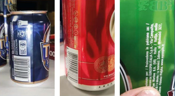
 Double image and registration
 Simple things can make a big difference
 WILDPACK STARTS PRINTING PRODUCTION OF CAN SLEEVES AND LABELS
 PANO SUCCESSFULLY COMPLETES METAL PRINTING MEGAPROJECT
 KOENING & BAUER PRESENTS ITS NEW METALSTAR 4
 NEW ERA IN BEVERAGE CAN PRINTING
 Operational Checklist
 Inkjet beverage can printing
 Seaming tooling for beverage cans
 New project metal cans


0 Comments