In most cases, this situation is something no can maker wants to see in their Decorator.
Almost every can manufacturer has a different approach, but most likely they all do the same thing to avoid this common problem.
Everyone likes to increase the printing pressure and print the can as well as they can. But sometimes this high and excessive printing pressure can cause some serious damage. Depending on the type of decorator used can affect this high printing pressure.
The Rutherford will resist this excessive printing pressure up to a point where even the Rutherford can no longer withstand the pressure.
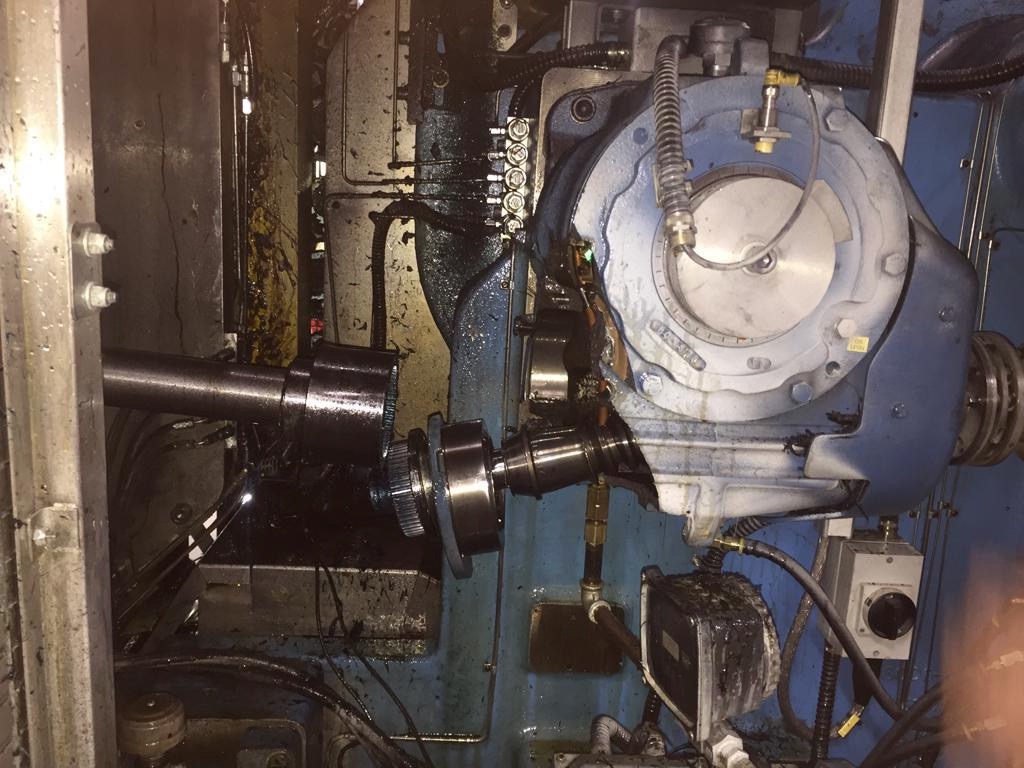
What can happen if the pressure is too high in a Rutherford can be seen in the image below.

Due to this excessive pressure the gearbox at the rear is destroyed and the spinning disk is jammed and damages the Mastercam and causes great cost to repair it again.
Now look at the cause of this failure, why this happens and what can be done to avoid this type of situation.
We know that the Rutherford is a more rigid design machine compared to the Concord, the key point in both machines is the chuck circle and parallelism.
A good mandrel circle on a Rutherford can reduce printing pressure, on the Concord two factors are important.
The first is the circle of the mandrel and the second is the parallelism of the mandrel arms.
Now we can see how we can check this and what to do to make sure that the printing pressure is as low as possible.
Check the chuck arm assemblies for looseness after the first year of machine operation and every six months thereafter.
If high printing pressures are used (0.05 bare blanket segment to bare mandrel), checks should be performed every 3 months or when voids begin to appear in the can impression.
- Before removing the arms from the mandrel:
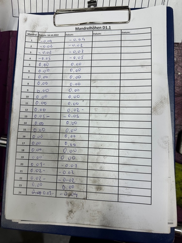
Place two (2) 0.001 indicators above mandrel #1, one at the open end of the can area and one near the dome end. Set both indicators at the high point of the mandrel. - Rotate the chuck turret while observing and recording the indicator readings on each chuck.
This is called checking the parallelism of the mandrel. If there is more variation more than 0.004 inches out of parallel on either mandrel, it may be suspect.
A. Wear or damage to the trip arm shaft or bushing/bearing area.
B. Wear or damage to the support arm shaft or bearings.
C. Wear or damage to the chuck, the chuck shaft, the chuck bearings, or the
mandrel arms. - If the mandrels are out of parallel more than 0.004 inches, and the mandrel arm bushings/bearings are known to be damaged; the mandrel arms should be replaced.
Note: The parallelism of the chuck arms can be checked on a bench on a granite surface with the support arm shaft inserted into the chuck arm and supported with suitable adjusting blocks.
With proper inspection, the chuck fixture can be checked in two planes using the chuck arm support shaft as a reference point.
This will be more difficult than checking on the turret wheel, and the functional readings will not be as accurate. - Disassembly of the chuck arm assemblies.
A. Remove two thrust washers 211245 each.
B. Press out the chuck shaft after removing the chuck shaft drive nut.
C. Press out the cam follower shaft. (Axial play is allowed in cam followers. Redial clearance limit is 0.001).
D. Remove the sham ban seal housing and sham ban seals.
E. Press the shaft plug out of the support arm shaft.
F. Press the bearings out of the support arm shaft.
Note: Never apply force through the chuck arm beam. Always support
under the bore of the bearing to be removed and push out the
bearing. Pressing through the mandrel arm beam can cause damage.
Important:
Do not remove the steel bushings from the mandrel shaft or cam follower shaft of the cam follower.
of the mandrel arm. If these bushings are damaged, the chuck arm must be discarded.
G. Remove the stop pin from the chuck arm.
H. Clean all parts that may be used when the arm is reassembled. All passages must be free of ink, varnish and debris.
This procedure is only when you are operating a Concord Decorator, the
Rutherford only needs one mandrel circle, and that’s it.
What is also important on both machines is the blanket segment wheel, the Concord has a removable one once made of aluminum.
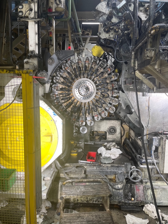
The Rutherford has one that is made of cast iron and in one piece.
In the event that something happens on the Rutherford segment wheel there is less
option to repair the problem.
In terms of design, it is a limited option to repair damaged segments, as you can see
below.
As the segment wheel is in one large single piece with 12 segments

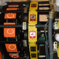
The Concord design has a different segment wheel, it is made with detachable aluminum segments, as can be seen below.- In case something happens, it can be replaced quickly and the problem will be solved in a short time.
image
After the machine has been operated for more than 5 years it is recommended to cut the blanket wheel to make sure that everything is in good condition.
Now look at how we can make the cut on a Concord Decorator.
It is absolutely necessary to remove the old segments beforehand, determine whether they are reusable, clean and deburr them. If the segments are more than 4 years old and
If the segments are more than 4 years old and have a 0.040-inch wedge under them, it is prudent to consider that they have lived their useful life. The same care should be used to clean and deburr the areas where the segments sit on the blanket wheel. If ink residue or ink residue or burrs remain, the segments will settle prematurely and the print quality will be unacceptable. Make sure the shims have been deburred (pn.302293 – .020 in., pn.301710 – .010 in.) and install them under the blanket segments. Tighten the blanket segments to 30 ft. lbs.
The average time required for this cleaning is 4 to 6 hours. The average time required to complete the blanket wheel turn to can plant specification is 4 hours. A minimum of 8 hours of downtime is required to complete this operation.
Lock the machine power supply!
Disconnect the ink drives and cover the inks with plastic or cardboard. Remove the form rollers from inking unit No. 3.
Remove the varnished envelope gear assembly, and the blanket wheel, gate guard and post.
Using the circumferential handwheel for station #3, position the steel portion of the plate cylinder drive gear so that it mates with the blanket wheel bull gear. (NOTE: The nylatron backlash gear must not be engaged with the bull gear).
Adjust the clearance to .008 between the bull gear and the plate cylinder gear by using a gauge on the plate cylinder gear and adjusting the plate pressure stop bolt on plate cylinder #3. After adjusting the backlash, make sure that all plate cylinder drive gears are engaged with the torus gear to mimic the print mode as closely as possible. At this point the nylatron gear should be coupled to the bull gear.
Install a clean plate cylinder on a clean plate cylinder shaft.
(Non-magnetic)
Mount the cutting device in the holes provided in the subplate for this purpose. There were no holes in the older machines.
In this case a magnetic base drill is required to drill 2 holes 5/8-11 x 1 inch deep at 55 ¾ inches and 59 ¾ from the right end of the subplate. The distance from the operator side of the subplate is 2 ½ inches. Tighten the mounting bolts only until the lock washers begin to flatten at this point.
CAUTION: The cutting attachment must be carefully squared and fitted to the blanket segment. This is done by mounting an indicator on the cutting area of the device and passing it over the print side of the segment. Adjust the fastening with the screws on the operator’s side near the base, until the segment indicates “0” from back to front. Tighten the device mounting screws and recheck the device. After this, the taper fit should be parallel to the leading edge of the segment. Perform the same procedure with the indicator on the leading edge of the segment. There are two lifting screws on the top and bottom of the operator side of the cutting device. Manipulate these lifting screws until the device is at “0” on the leading edge. Recheck the reading across the print side. Correct if necessary.
Install the cutting tool in the fixture and hook it into the blanket segment. The tool should be set to take a minimum cut, approximately .001 in. This will allow you to readjust the taper setting for the segment (closer to the operator side of the plate cylinder). Measure between the plate cylinder and a blanket segment with a feeler gauge to determine the correct taper.
WARNING: YOU WILL BE WORKING IN AN UNCALIBRATED AREA, USE EXTREME CAUTION.
You can now reset the power and run the decorticator at 800 or 1000 c.p.m. to cut the blanket segments to the specification of the can plant using the formula:
Thickness of the plate on the image .032
Blanket thickness + .077
.109
Image printing to blanket – .004
Finished free space .105
This example shows that .105 inches should be obtained between the blanket segment and the bare plate cylinder by cutting the segments.
The highest quality printing requires controlling the thickness of the plate image as closely as possible and using only the highest quality blankets.
Note: The next step will add 3 to 4 hours to this procedure.
If replacement segments are to be cut, remove two finished cut segments at 180 and mark the segments for installation at the exact location where they were removed.
Install a 0.015-inch shim under the two segments to be cut as spares. Using the above example, the replacement segments would be cut to .100 in. of clearance between the blanket wheel and the plate cylinder with 0.0005 in. of toe-in at the operator end. Remove the replacement rings and shims and reinstall the original rings.
When replacement segments are used, they will need to be shimmed and leveled with approximately 0.010 inches of shims.
Remove sharp edges from all blanket segments.
Turning Fixture – Turning Fixture
This now shows us what the difference is between the Rutherford and the Concord Decorator.


0 Comments