In the past, the decorator speed was between 600cpm-1300cpm and the average label change was between 30min-45min.
But as the market and demand for cans has increased, the production speed was not enough to produce cans at lower speed, so the whole process was in the process of innovation.
In the past, labels were only 4 colors and the design was not as complicated as it is now. In the early 1970s, label design was minimally flexible, between 2 and 4 colors at 400cpm. Then, in 1980, there was a big change, since it was possible to have more than 4 colors.
It was possible to have up to 6 colors and screen printing at 85 lines/inch. In 1990 the printing industry took another step forward by having 6 and up to 8 color printing on the can. At this stage design became more and more critical and a photographic quality image could be printed on a can at higher speed. From the year 2000, 8-color printing became a standard with many different designs and many different coating possibilities on the market.
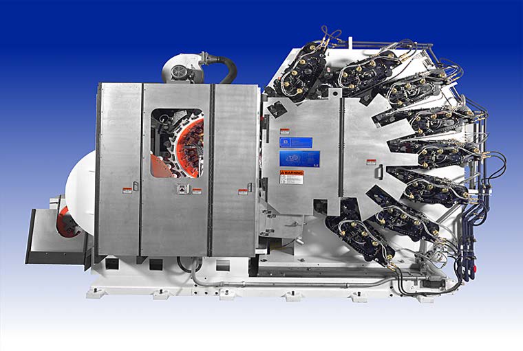
Now there was an innovation available, the DPI technology.
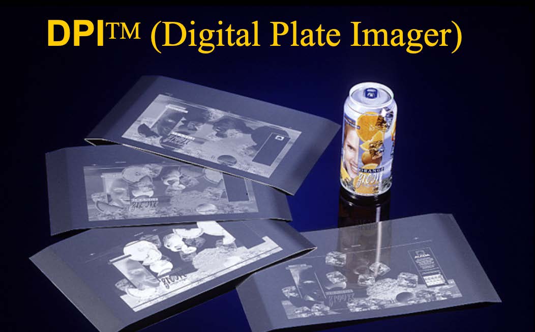
This new development now allows to have more lines per inch, in the early seventies it was only 85 lines/inch, but now with this new technology the lines per inch were 200/inch. This 200/inch or even more now allows the can maker to print in halftone with the smallest front print with a 1 point (.0014″) font. But the biggest impact for can makers now is faster label changeover, increased speed for complicated labels and greater profit potential.
—- photo —-
In addition, the cost of the plate was reduced, and it was now possible to manufacture the plate just in time. Ink inventories are reduced, the service life of printing blankets and rollers is increased and, finally, printing pressure is reduced. The principle of DPI is the ability of the plate to attract ink in one area and reject it in another. Ink repelling surface and ink attracting surface.
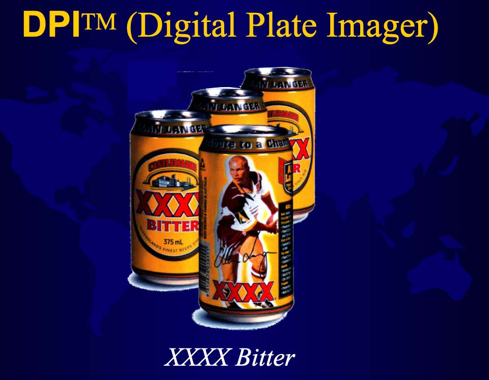
Laser energy – Laser energy
Imaged Area – Imaged Area
Silicone Oleophobic Layer – Oleophobic Silicone Layer
Image Forming Layer – Image Forming Layer
Ink Receptive Layer — Ink Receptive Layer
Aluminum Base – Aluminum Base
The use of high-power semiconductor laser diodes vaporizes the image-forming layer, releases the silicone and exposes the ink receptive surface. The plate is virtually flat, with only a few microns separating the imaging and non-imaging areas. The image goes directly from the computer to the plate, eliminating many steps that can introduce defects, reducing the number of repetitions.
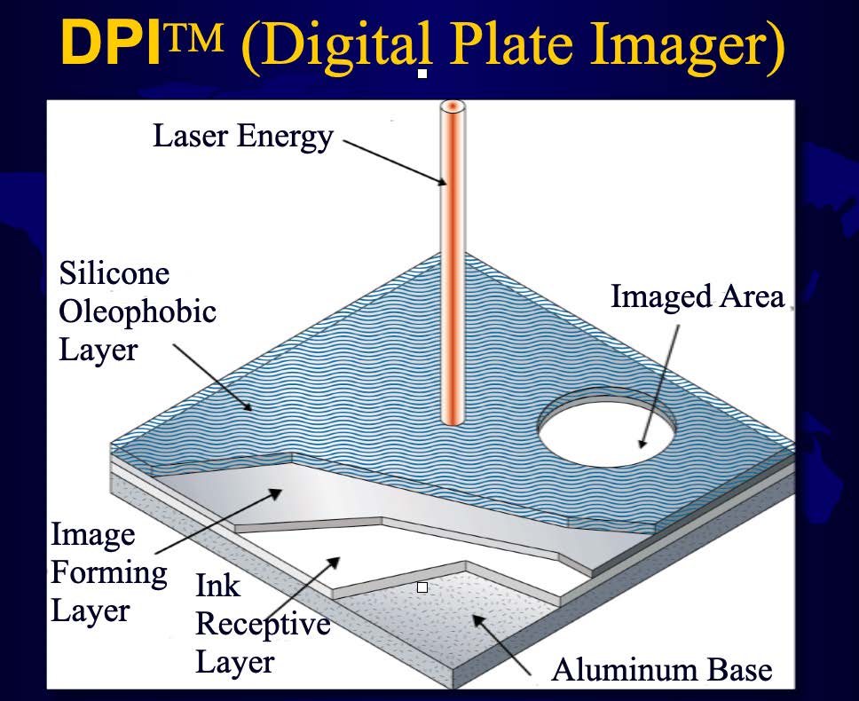
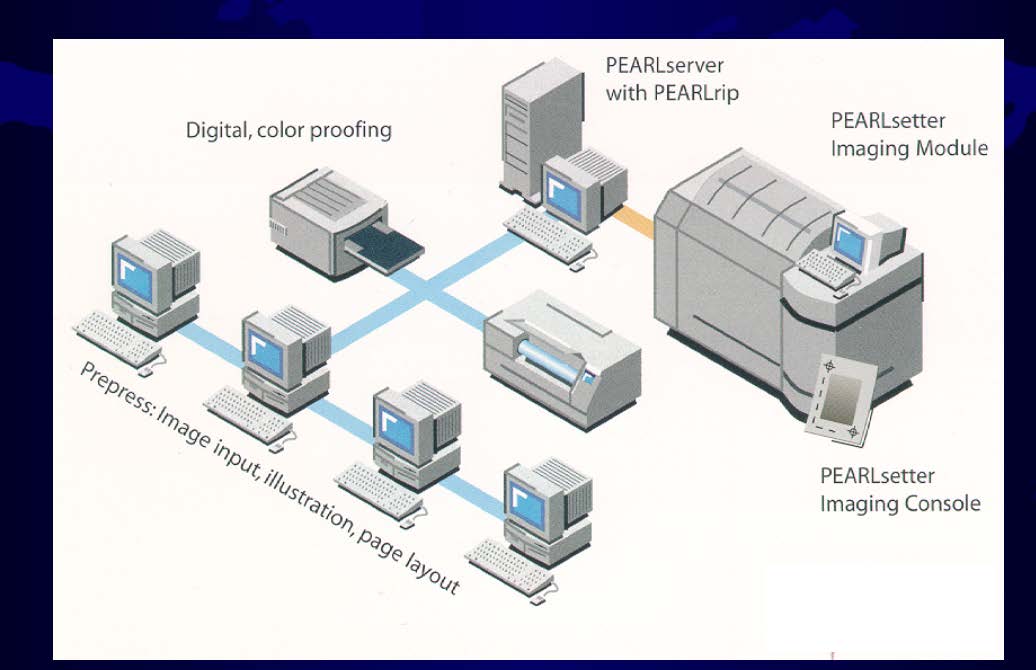
Digital, color proofing – Digital Color Proofing
PEARL server with PEARL rip – PEARL server with PEARL rip
PEARL setter Imaging Module – PEARL setter Imaging Module
Prepress: Image input, illustration, page layout – Preimpresión: Entrada de imagen, ilustración, diseño de página – Prepress: Image input, illustration, page layout
PEARL setter Imaging Console – Imaging Consoles PEARL setter
—-
After this process it can go directly to the plate cylinder to be mounted.
The plate can be produced in 4.5 minutes, after that the plate cylinder with the image on the plate goes to a two-piece can decorator.
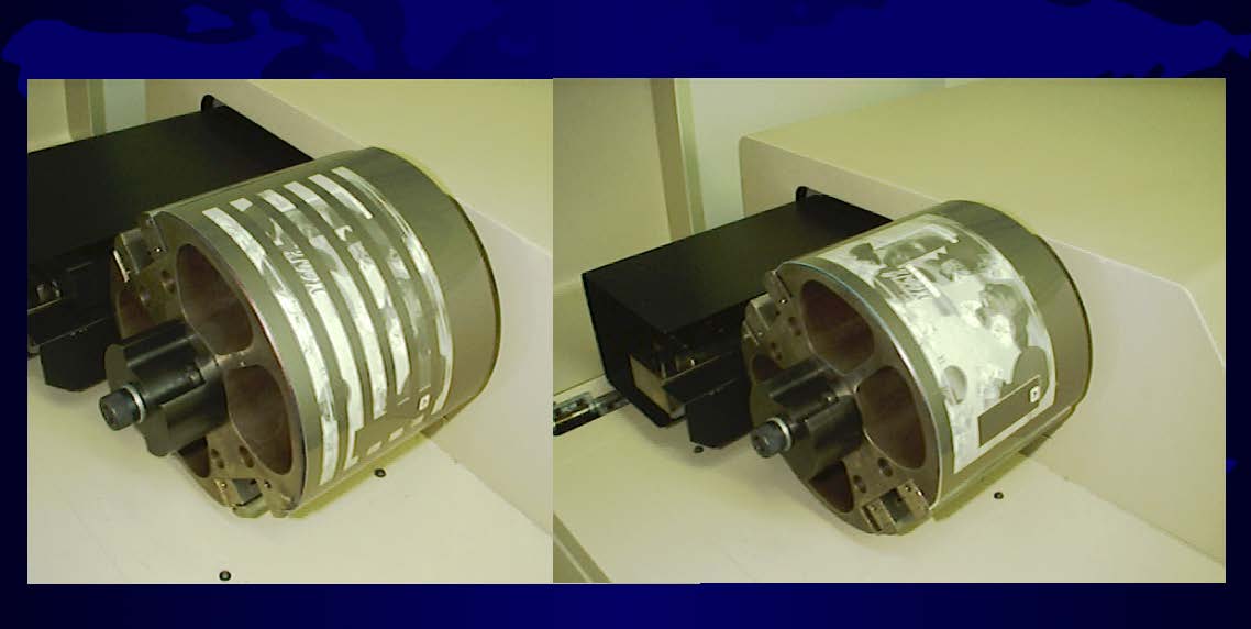
The image plate will then transfer the image to the blanket.
All plates on Concord Decorator in a very close register so it is very important to use DPI technology to make the plate.
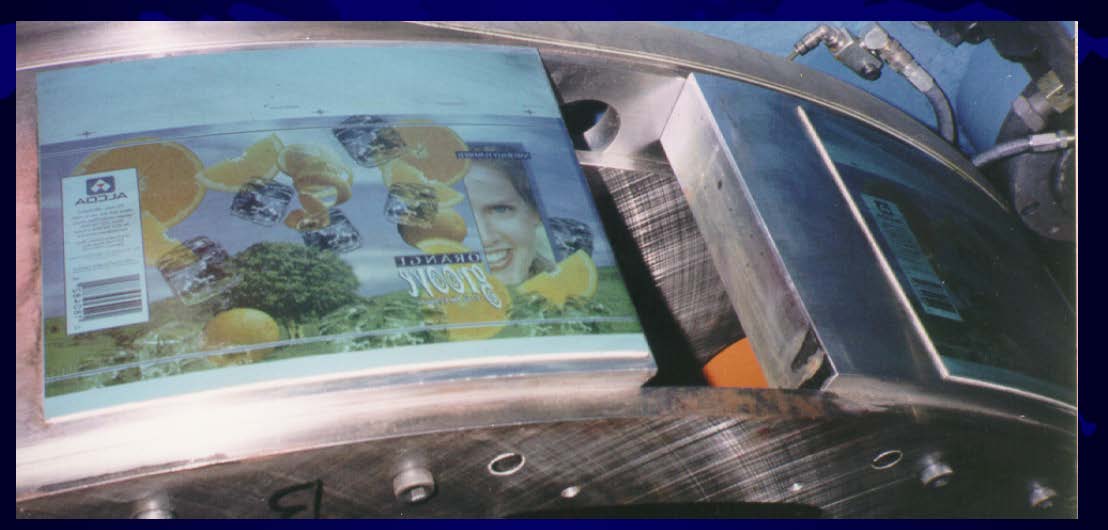
What is also important in today’s high quality printing process is to keep the machine with as little vibration as possible.
Since vibration can cause dot gain and high printing pressure which can lead to higher temperature on the rubber rollers, as well as transfer color contamination and, last but not least, registration problems.
What the effect of vibration looks like:
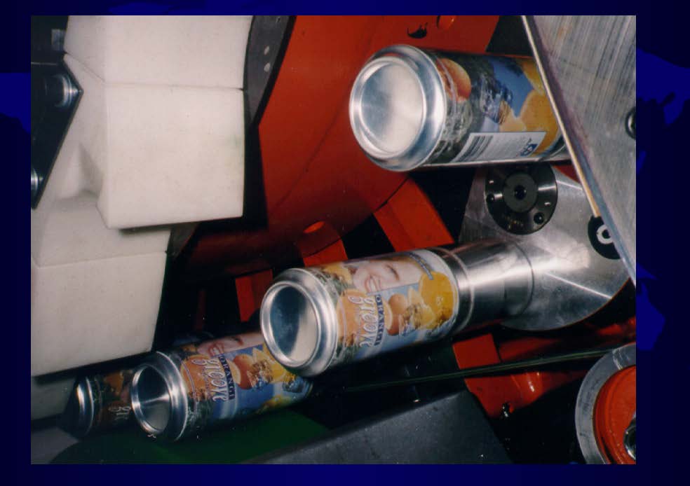
Effects of Vibration – Effects of Vibration.
The impact of vibration is more visible on a Rutherford than on the Concord, as there is the chuck, which weighs 2.5 kg, the Rutherford moves the entire carriage, which weighs 14 tons. the Rutherford moves the entire carriage, which weighs 14 tons, so the Concord prints more smoothly than the Rutherford.

Printing Implications from Vibration – Implications in Printing by Vibration
Clarity – Clarity
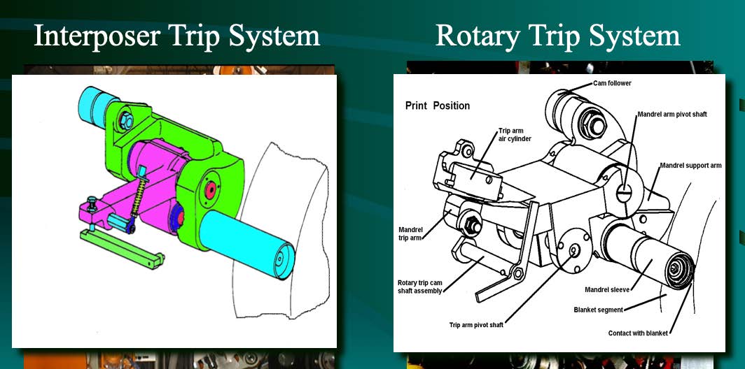
Interposer Trip System – Interposer Motion System
Rotary Trip System – Rotary Motion System
- Print Position – Print Position
- Cam follower – Cam follower
- Mandrel arm pivot shaft – Mandrel arm pivot shaft
- Mandrel Support arm – Mandrel support arm
- Mandrel sleeve – Mandrel sleeve
- Blanket segment – Blanket segment
- Contact with blanket Contact with blanket
- Trip arm pivot shaft – Pivot shaft of the motion arm
- Rotary trip cam shaft assembly – Rotary trip cam shaft assembly – Rotating trip cam drive
- Mandrel trip arm – Mandrel trip arm
- Trip arm air cylinder – Trip arm air cylinder – Motion arm air cylinder
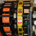
This picture shows the motion system, in which only the motion arm moves forward to print the can, thus the vibration is less than in a Rutherford.
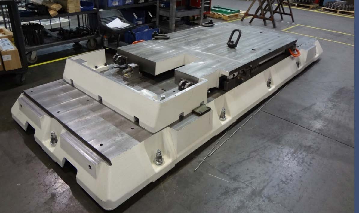
The Rutherford moves the entire carriage to achieve the same effect, but with one big difference.
This photo shows just the carriage with nothing on it, more parts will be installed and the final weight will be around 14t to move in and out and this is the cause of the vibration.
However, the greatest impact is generated in dot gain caused by heavy printing pressure.
This high printing pressure can also cause embossing blanket and roll form enhancement.

Another side effect of printing pressure is stretching of the image, as the plates are very long.
The circumference of the can is approximately 8.1875″ and the image length is 8.125″ to 8.250″.
This is slightly different in a Rutherford, as they only use one plate instead of two plates in a cylinder.
The Rutherford’s prefer to have the dimensions match the specifications to achieve the correct image length.
CONTACT WITH GEAR: – Is the diameter of the impression cylinder with the plate mounted 5.000″?
Are the blankets per specifications 0.076″ to 0.077″ (1.95mm)? If either is greater, the gear contact will be reduced. If either is out of specification, the blanket speed will be different from the plate speed. This can manifest itself as a poor fit of the plate between solid and other colors. Excess printing pressure will alter the print length of solid colors, pushing the rubber blanket forward or backward, depending on specifications.
Dimension should be: 5.243 maximum (133,172mm)
5,240 minimum (133.096mm)
Any dimension reading beyond this tolerance will be attributed to variations in the print length of the plate cylinder driven by the out-of-specification gear.
As well as the slippage between the speed of the plate cylinder and the speed of the blanket wheel must be equal otherwise the image will have spots.
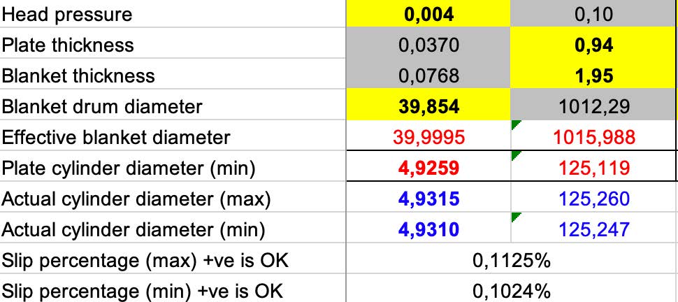
Head pressure – Head pressure
Plate thickness – Plate thickness
Blanket thickness – Thickness of the blanket
Blanket drum diameter – Blanket drum diameter
Effective blanket diameter – Effective blanket diameter
Plate cylinder diameter (min) – Diameter of plate cylinder (min)
Actual cylinder diameter (max) – Actual cylinder diameter (max)
Actual cylinder diameter (min) – Diameter of the actual cylinder (min)
Slip percentage (max) +ve is OK – Slip percentage (max) +vo is OK
Slip percentage (min) +ve is OK – Slip percentage (min) +vo is OK
The goal is to keep the diameter of the plate cylinder along with the plate close to 5,000.”








0 Comments