SUMMARY
This device is an automatic device for aligning the punched pieces, in their proper position, on the press output conveyor, and stacking them later.
INTRODUCTION
The upper end or cover of the batteries – dry electric batteries – is the element that surrounds the positive pole of the batteries. They are pieces so small in size and light in weight, that when they fall on the conveyor of exit of the press, they can do it mouth up or face down. Therefore they are difficult to sort and align all of them in the same position, for proper stacking.
The present work describes a team developed to do this task automatically efficiently, which results in a significant reduction in manpower. We will call this device from here “aligner”
DESCRIPTION OF THE OPERATION OF THE ALIGNER
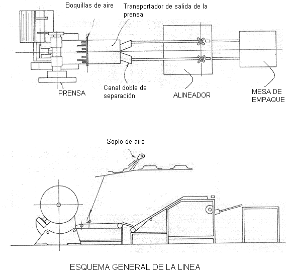
See figure # 1 to follow the work process
Figure nº 1
a.- The alignment equipment is installed behind the press outlet conveyor. The link between this conveyor and the aligner is made by means of a two-row separation channel.
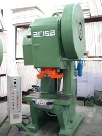
b.- The press used for a work of this type, is an automatic press of simple action, equipped with multiple useful – of 5 punches – at a rate of 150 strokes / mi.
c.- The stamped covers of the batteries fall from the press without order on a conveyor.
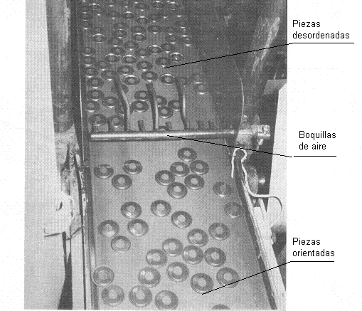
d.- To ensure that the external faces of the same, are always up on this conveyor, pressurized air is blown through nozzles, as shown in the central part of Figure No. 1. In the following photo – figure # 2 – this assembly is seen.
Figure nº 2
e.- The pieces, once oriented and aligned in a certain direction on the conveyor, can be inspected by a vision control system. It can reject the defective ones.
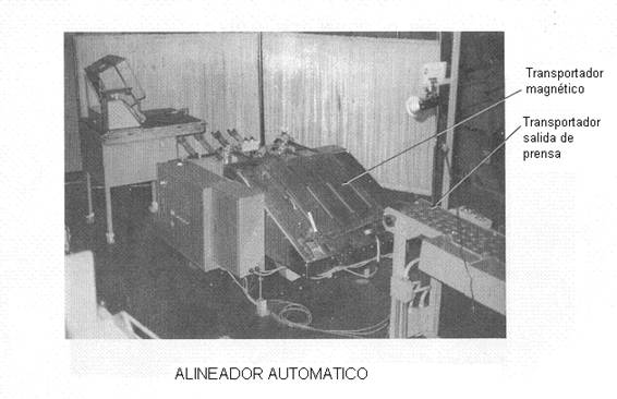
f.- The covers are passed through a double separation channel, which distributes them in two rows, depositing them in a double magnetic conveyor in elevation.
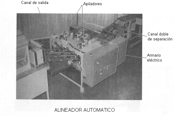
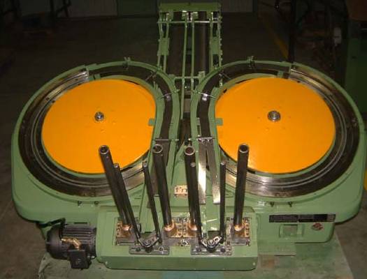
g.- The elements arrive at a pair of stackers, located at the end of the double magnetic conveyor. A permanent magnetic pulley is mounted under each stacker. It collects the pieces of the stacker, and moves them to an exit channel.
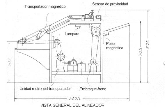
h.- To ensure that a predetermined quantity of elements is stored in each stacker, the magnetic pulley is controlled by an electromagnetic brake-clutch, which acts when the proximity sensor-meter-placed on the stacker detects the anticipated amount. In figure 3, which represents a general view of the aligner, you can see the elements indicated here.
Figure nº 3
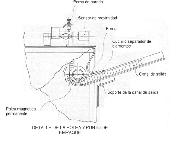
i.- At the exit of the magnetic pulley, a brake retains friction parts, so that they remain grouped. Next a separating blade is located, which also acts with the sensor and separates the number of pieces counted.
j.- The stretches of covers already counted, when arriving at the exit channel, are “skewered” by the central hole, with the help of a rod and introduced in cardboard boxes.
See detail of points h, i and j in figure 4
Figure 4
CONSTRUCTION OF THE ALIGNER
The aligner consists of two equal rows of devices, working in parallel, capable of ordering, aligning, counting and preparing to be packed the battery covers. Each of the rows works at a speed of 375 pieces / mi, that is to say at a total rate of 750 pieces / mi.
As it is clear from the operation description, this equipment consists of a series of assembled elements, which are listed below:
– Air blower nozzles, located on the press outlet conveyor. Its function in ordering the position of the covers, turning those that are inverted. These nozzles are an independent element of the actual aligner.
– Magnetic conveyor in elevation., That transports and elevates the pieces.
– Discharge coupled to the end of conveyor.
– A proximity sensor that activates a counter, located above the discharge.
– A storage stacker
– A magnetic pulley
– An output channel of the magnetic pulley, provided with a parts brake and a separating knife.
– A packing point
– Electricity cupboard.
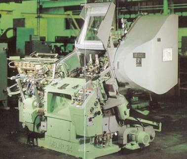
In the following pictures, figures 5 and 6 show two views of the team
Figure nº 5
Figure nº 6
In addition, independently of this device, a vision quality control system can be mounted on the conveyor.
SPECIFICATIONS
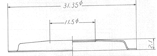
A.- Size of the covers: See figure No. 7
B.- Capacity: Max. 750 pieces / mi.
C.- Power: 0.75 Kw.
Installation space: Width = 850 X Length = 1.475 X High = 875 mm.
Weight 210 Kg.
Labor savings: 2 people / shift






0 Comments