SUMMARY
Some criteria and recommendations for the construction of different types of dies for embutition packaging.
PREAMBLE
Within the metal industry, the manufacture of sausage-type packaging may be the most reliable and affordable technique. Its use dates back to the beginning of this industry, although it has always suffered the limitation of the limited range of formats available, since the way of manufacturing requires to prepare a specific tooling for each size of boat.
There are different options to manufacture embedded packaging. The most recent is the so-called DRD, intended for high-altitude boats in relation to their diameter. In other works of this Web we have already discussed this way of operating, therefore we will not enter here again in this matter.
In these lines we will focus on low-height packaging, especially in the two variants of its manufacture and in the characteristics of the necessary tools.
WORK MODES
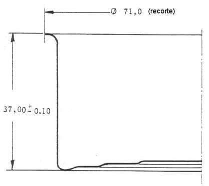
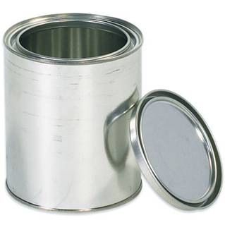
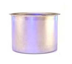
We understand as low-rise containers, those that it is approximately equal to or less than half its diameter. For example, the container that we will take as reference in this article, the one that appears in the drawing # 1, would be a limit case within this group.
These containers can be obtained in a single pressing operation, although it is possible to choose a second operation to cut the excess material, or to include the latter in the same drawing operation.
Therefore there are two ways of working for these types of boats, in single-operation or double-operation installations. For your study, we will take as an example the container RO 65 x 37, whose final external dimensions are indicated in drawing no. 1.
Drawing nº 1: External dimensions of the container RO 65 x 37
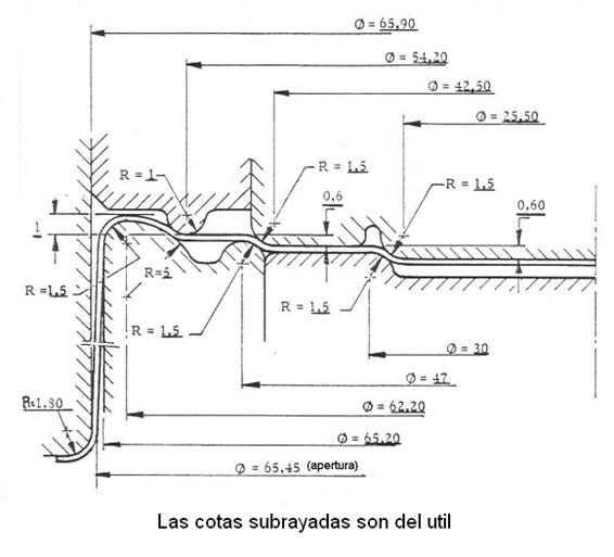
Whether the process is done in two operations or in one, the core of the forming die presents the same measures, as they are what shape the container. In the drawing no. 2 the same are indicated for the boat that we have taken as reference.
Drawing nº 2: Measures of the pieces that shape the container
The dimensions that appear in the drawing no. 2, all correspond to the pieces of the tool, appearing underlined, except the opening diameter or mouth of the container that is measured as a boat. The pieces that shape the container are basically three, the punch for its internal face, the center of the matrix and the center of the punch.
In spite of the equality of measures in the forming part of the packaging in the two possible manufacturing processes, there are substantial differences in the design of the dies in both cases. Let’s see these differences.
IN TWO OPERATIONS
When the container is completed in two operations, the task performed by each of them is:
– 1st operation: Cut the disc of material from a flat strip, embed and shape the container.
– 2nd operation: Cut the excess ring of material on the edge of the boat, it has an irregular edge due to non-uniform stretching of the metal. These are always higher in the rolling direction of the same in the steel industry.
Conceiving manufacturing in two operations, simplifies the design of the dies in both, although it is necessary to have two presses and their joining elements, and therefore greater physical space in the industrial warehouse.
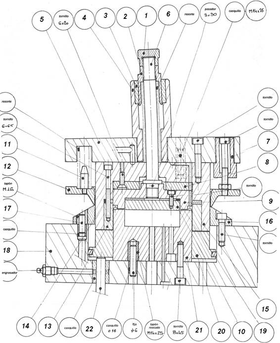
The tool of the first operation consists essentially of a couple punch and cutting blade – pieces 15 and 16 of drawing No. 3 – and the centers of punch and matrix that give shape to the container – parts 9 and 21 of the drawing -. In this design, the center of the punch – # 9 – also acts as ejector of the container at the end of the process. These pieces can be enhanced by improving their performance, as is the case with the cutting punch, which is formed in turn of three parts: cutting punch itself – 9 -, inner ring forming the container wall – 13 -, and shoes – 14 – The latter allows sharpening the cutting edge of the punch without having to redo its inner part, adjusting the height of said shim after each sharpening.
Drawing nº 3: Die 1st operation – cutting and drawing.
The tool is completed with the tread – nº 12 – and its complementary parts, the base plates – 5 and 18 -, the punch holder – 4 and contiguous, – and the lower pressure system. Of the latter only the piece nº 22 is seen in the drawing, the rest would be in a lower plane and because of its simplicity it has been dispensed with due to the problem of space.
It is also necessary to add a shim – No. 8 – to adjust the position of the center of the punch when the cutting edge of the punch is rectified, and therefore its height is affected. The tool is finished with the springs, fixed, pins, etc. necessary to ensure their actions, alignment of parts and operation.
The tool of 2nd operation is simply a set of punch-cutter blade, complemented by a feeding system of the container in correct position. The evacuation of the can is done through the blade, for which the lower part of the die is hollow at its center. We do not consider it necessary to present a drawing of it given its simplicity.
IN AN OPERATION
When we choose to finish the container in a single operation, we must incorporate the action of cutting in it. Therefore, it is necessary to resort to providing the tool with a double effect, which allows cutting the remaining material in the final section of the carriage of the press.
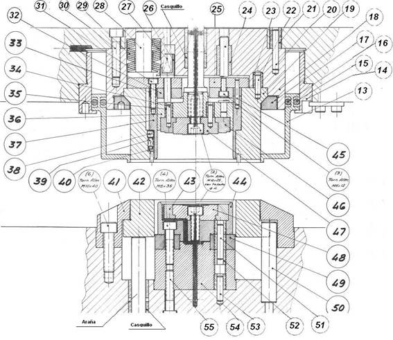
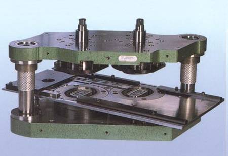
For which the die is added, in addition to the pieces in charge of the initial and consecutive cutting embutición – punch, blade and centers of matrix and punch -, other new pieces that perform the action of the final cut. The latter is achieved with the incorporation of a second cutting edge inside the punch, which acts as a moving blade, which operates on a fixed punch positioned below the center of the matrix. In the drawing no. 4 a die of this type appears that we will now describe in more detail.
Drawing nº 4: Die in a single operation, cutting, drawing and trimming
In this drawing we have dispensed with the upper area of the punch – punch holder – and the lower part of the matrix – pressure system -, to simplify the drawing, but we must bear in mind that they are essential and therefore it is necessary to have them .
The punch is formed by two basic parts, No. 19 and 37 of the drawing, the 37 is the internal part thereof, which forms the outer wall of the container body. Both pieces, in their resting position, are flush at their top and bottom, for it on No. 37 is acting a flexible system of pressure of great power, obtained by the action of a set of elastic conical washers, pieces No. 29 Thus, a double effect on the package is achieved. This way at the time of cutting and drawing both pieces 19 and 37 work in solidarity and level, carrying the metal well controlled with the help of the ring nr 42. In the last millimeters of the travel of the carriage of the press, piece 37 remains halted on encountering the piece 49, located below the center of the die, this piece 49 is a fixed punch that strikes the internal edge of the piece 19, causing the cut of the ring of excess material. At this moment the piece 37 has overcome the action of the elastic washers and by means of the 25 has made solid stop with the upper plate 18.
The cut-up rises pushed by the presser 42 and is then ejected by the small ejectors 40, housed in the punch and driven by the springs 39. A good delivery system of the container and cutting of the vertical of the die, towards the discharge channel, mechanical or pneumatic, must ensure that there is no danger that in the next stroke of the press is “caught” said cut.
The die is completed as is logical with another series of pieces, such as:
– the centers of punch and matrix that form the bottom of the container,
– the external treadmill, which in this case is pneumatically operated
– Lower pressure system – spiders.
– pressurized air circuit for the control of footfalls
– trapped air evacuation hole system
– punch holder
– bushings, pins, stationary, guide columns, etc.
The lower cutting punch – 49 – can be made with a cutting edge on both sides, to prolong its useful life. The design presented in the drawing allows disassembling the upper puncture without the need to lower the die of the press, for this it is enough to disassemble the treadle by loosening the piece 14 by means of a special key, since said piece is threaded to the upper plate, and once extracted the same do the same operation with the piece 17 which is also fixed by thread on the 18. To ensure a good fixation, the contact between 19 and 17 is by means of use conical surface.
When the punch 19 is disassembled, it is possible to rectify its cutting edges. When this piece loses height it is also necessary to adjust the lower lip of the piece 37. In this case, in order to keep the height of the container constant, the thickness of the shim 32 must be lowered in the same loss.
Due to the precision required of this die, when making a double cut, the construction of it is of high precision and has to be of course a tool with guide columns.
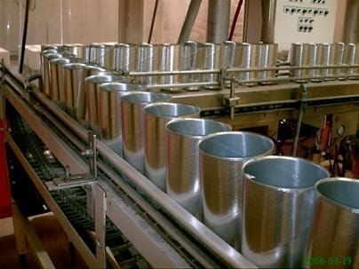
In order to separate the containers from the clipping rings, it is necessary to dispose at the exit of the press a section of fall by gravity of thin and separate rods, which allow to pass the cut through them. Sometimes they arrive cuttings to the transporter of packaging, and to eliminate totally the same, a possible solution is to place a intermediate conveyor a little higher, and leave a space between both transporters. The passage of the containers from one conveyor to another, will be done by gravity, supporting the container only by its flange by means of two round rods. For the system to work well, it must be ensured that all packages arrive at this point face up, which is easy using a previous system of sorting “doors”, such as those used in vibration feeder tanks.





0 Comments