
SUMMARY
New work, within a series of them, for productivity improvements. This deals with how to feed manually and in a simple way, a first operation press, in a manufacturing line for embedded packaging, with a sensible saving of metal.
INTRODUCTION
The conventional way of manufacturing a low-height stuffed container is to perform the same in two operations. In the first one, the disk is cut, the embossment and the conformation of the profile of its bottom, that is practically all the container is made. But due to uneven stretching of the tinplate or TFS, the flange or edge thereof presents an irregular appearance. Therefore, to cut this edge requires a second operation, leaving it to the appropriate size and equal in all its parts.
For low production rates, the first operation is carried out in a manual or automatic press, equipped with a stroke of the crankshaft and a lower pressure system suitable for an embossing job. This press is fed with tin strips, which for easy handling require a cut or over measure in relation to the proper cut to stuff the container. This trimming is necessary both in the width of the band and along it, ie between cutting and cutting. The same, among other functions, allows to extract the waste of the band in a single piece without generating jams. Said surplus receives different names in the metal slang as: cut, skeleton, skewer, etc. When the stuffed container is round, the loss of material for this concept is very important. See figure # 1:
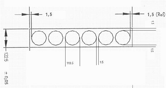
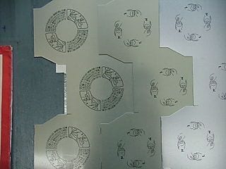
Figure nº 1 Example of trimming on a strip
One way to reduce this trimming is to cut the zigzag bands. It is the ideal but expensive solution, because it requires having equipment and tools suitable for it. There is another much cheaper alternative that is what we now detail. It is designed for small installations with little activity. In it, four elements must be implemented:
– Manual press in horizontal position.
– Strips cut with special measures.
– Feeding by gravity.
– Modification of tooling and stop.
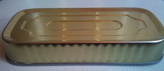
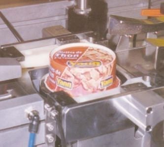
To follow the topic with more property, we will do it by means of an example. Let’s suppose that we want to carry out an installation to manufacture small series of an embossed container of dimensions RO 71.5 x 27 according to drawing no. 2.
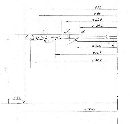
Figure nº 2: Inlaid container RO 71.5 x 27
PRESS
For the first operation, we will need a manual press of approximately 40 tons, of at least 75 mm of stroke, equipped with a pneumatic cushion, installed in a horizontal position. The latter for our case is fundamental. The horizontal position is necessary to allow a feeding of strips in a vertical plane as we will explain later.
Not all presses can be tilted to the horizontal position, but with some modifications it can be achieved. For example, adding supports or back legs on which rest the back of the body of the press.
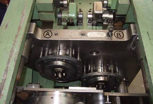
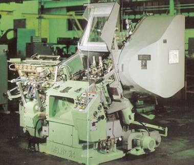
We will not enter the rest of the machines of the line, since they do not have any particularity. An example of this type of installation can be seen in drawing # 3.
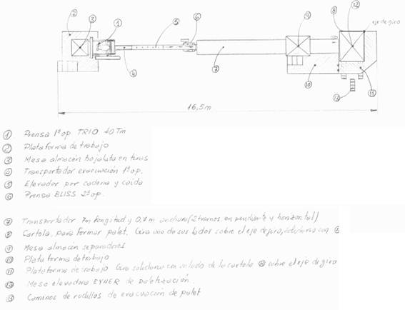
Figure nº 3: Small line of sausage packaging
DESIGN OF THE TIN SHEAR
To define the dimensions of the sheet metal we will consider the following:
– The strip width will be smaller than the cutting diameter of the mortise. A supported rule is 1 mm smaller than the cut. In our example being the 119.5 mm cut the strip must have 118.5 mm. This supposes an important saving, since in normal conditions it would be the cut plus 3 mm. It means a saving of 3.4% in width.
– The distance or step between blow and blow, will be exactly the cut. Therefore we save the usual cut between cutting and cutting. This supposes a reduction of 1.25% of material in length.
– With these premises, we will determine the cut diagram and the appropriate sheet size. In figure 4 we represent the one corresponding to our example.
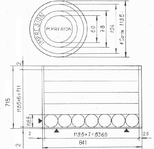
Figure nº 4: Diagram of cut and dimensions of tinplate of RO 71.5 x 27
For this case, if we compare this sheet dimension, with what we would obtain with conventional trimming, the savings exceeds 4.5%, which is enough when we talk about the cost of the basic raw material.
FOOD OF THE PRESS
To feed the strips to the press, in our example of dimensions 118.5 x 836.5 mm, we must take the following actions:
– Prepare a platform for the operator, with sufficient height for the press to be at a low level. The tool should be more or less at the height of the knee. In this way, when the operator takes the tin strip of the pallet, to deposit it in the feeding channel, it will not be necessary to raise the arms, since this would produce extra fatigue.
– The strip feeding channel or hopper will be mounted vertically. The vertical feed plane is defined by the cutting edge of the drawing die blade. This channel is formed by simple guides, which control the strip in all its senses except in the descending one. Its upper mouth will have a hopper or funnel shape, to facilitate the introduction of the strip. The operator will deposit the band in the channel, releasing it immediately; it will descend to find a stop, on which later we will return. If the band is very heavy, you may need light brakes, which cushion your fall. They will be made of a material that does not scratch or mark the varnish of the strip, such as felt, leather, etc … Figure 5 shows all these components schematically.
– On the platform a table will be placed to receive the pallet of cut strips. The operator will take the strips one by one and release them into the hopper. It is not necessary to synchronize the fall of the same, because if it falls soon it will stumble on the punch, which at that moment is embedding the last container of the preceding strip, and wait for it to rise to position on top of the matrix. If it arrives when the punch is rising. it will stop the stop, staying in the correct position.
– Under the press, a container will be placed to collect the pieces of trim that fall.
– A discharge guide will receive the containers when they leave the die and deposit them in the evacuation conveyor.
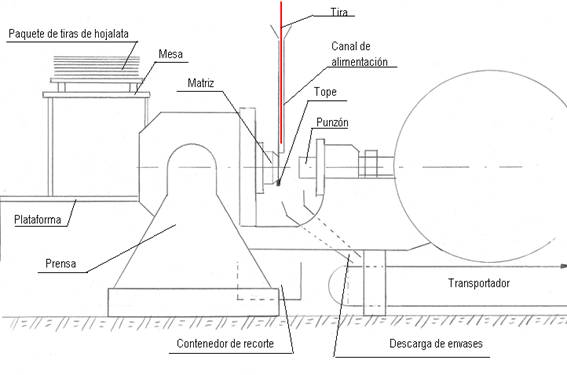
Figure nº 5: Press installation diagram 1st operation
The press must be provided with the adequate protections to guarantee its safety, as well as controls on the exit of containers or jamming.
MODIFICATION OF TOOLS AND STOP
On the underside of the tool, a stop must be mounted just in line with the cutting edge of the blade. See figure # 5. On its descent, the punch will rub gently, without damaging its cutting edge. In this way the strip will break by three points in each punch stroke. A point will coincide with the stop, that is to say in the lower part of the same, since when the cut occurs, as there is no cut, the break will be generated. The other two points will be positioned on both sides of the strip, since its width is smaller than the cutting diameter.
As a result of all this, two pieces of tinplate cut appear in the form of curvilinear triangles, which will fall below the container discharge guides, to the collection container.
When raising the punch, the tin strip will fall back down, in a path equal to the cutting diameter until the stop stops it, and the cycle will repeat itself.
RESULTS
In this simple way, a double objective is achieved:
– Get an acceptable material savings
– Make sure that the operator works continuously, with foot pedal pressed, in a comfortable way, since his task is limited to dropping strips through the guide hopper. Thus it is possible to work at the maximum speed allowed by the press.
 DIE FOR ENDS
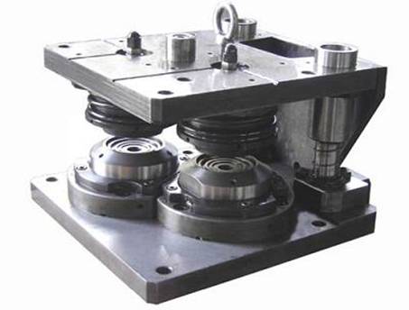
 DIE FOR EMBUTITION PACKAGING
 LINE FOR PACKAGING “PARTY”
 PACKAGING IN SMALL LINES OF EMBUTITION PACKAGING
 DEEP EMBUTITION FOR AN INVESTED SYSTEM
 CAN LINE “TWO PIECES DRD”
 TOOLS FOR PLUGS Paint containers
 CALCULATING THE PROFILE OF A CUT IN ZIGZAG
 PREVENTIVE MAINTENANCE OF AUTOMATIC PRESSES


0 Comments