Index:
– Chronology
– Fundamentals of electric welding
1º.- CHRONOLOGY
a) START
In the early 1960s, two different welding processes were developed more or less simultaneously, without adding alloy, for commercial purposes, to join the side edges of “three-piece” cans.
This welding process is based on supplying a certain amount of energy to the areas to be joined in a given time. This energy is transformed into heat capable of melting the metal parts to be welded. The energy is supplied by means of an electric current and the process triggered is very well studied by the laws of Physics.
Continental Can introduced the «Conoweld”. This technique was initially used for the production of steel beverage cans with electrolytic chromium coating (TFS). To perform satisfactory welds with the first machines, the steel surface was required to have no chromium coating in a width of about 2 mm on each side of the edges forming the seam.
At approximately the same time, Soudronic AG of Switzerland introduced semi-automatic electric seam welding machines for tinplate. These first Soudronic welders were used in the manufacture of large metal containers for general products. The side seams overlapped up to 4.5 mm, producing what became known as “Butterfly” welding (see figure below). This “Batterfly” welding was not suitable for food containers, as it was found that there were great difficulties in varnishing the pronounced edges of the seam. The thickness of this type of welding was so high that it could not be covered by a layer of varnish, however high the load of this was.
b) SOUDRONIC WELDING DEVELOPMENTS
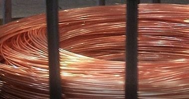
By the mid-1960s, Soudronic had introduced fully automatic machines for the production of medium and large-sized can bodies. In 1969, the Company introduced faster machines for the manufacture of aerosol containers, producing 200 units per minute. However, perhaps the most important contribution took place in 1975, with the “profiled” wire mash welding system (WIMA). This technique involves the use of a drawn and flattened copper wire, so that the contact surface in the welding area is increased, producing a more solid and adequate weld, with a flap of only 1 mm wide (see figure l). Soudronic developed the use of copper wire as an intermediate electrode between the can seam and the copper welding wheels, to solve the problem of electrode surface contamination and its effects on weld quality. As the wire is not reused, electrode contamination ceased to be a problem. On the other hand, the waste wire has a high economic value. The wheels were mounted with an inclination of 2º, to slightly chamfer the edge of the seam and thus reduce the step and facilitate the re-varnishing of the same.
These improvements allowed can manufacturers to produce side seam cans by welding without alloy for the first time in the food industry and other demanding applications.
Figure 1: Different types of electric welding in side seam
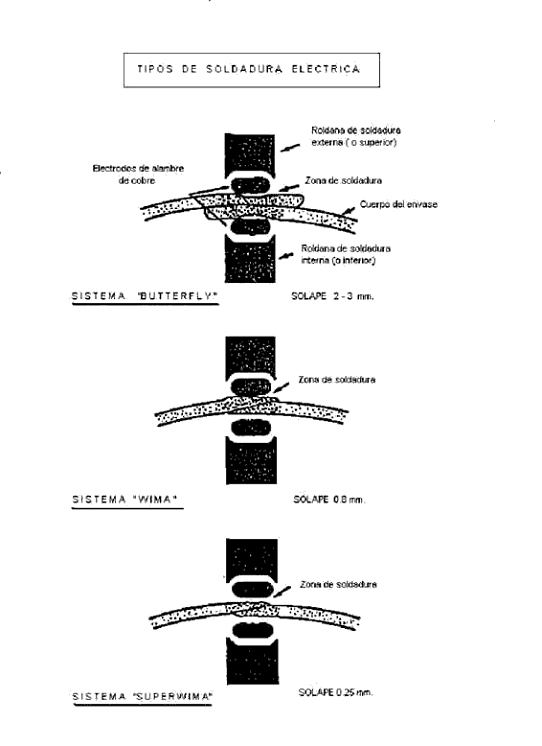
In 1978, the SUPEWIMA welding system was introduced. This development of the welding process needs an overlap of only 0.15-0.3 mm in the side seam. To this must be added other advantages: reduction of the welding area affected by heat; less hardening, and reduction of the thickness of the seam (approximately 1.2 x plate thickness). Along with greater efficiency in the welding process, improvements were made in the speeds at which the machines could operate, being able to produce more than 500 containers per minute.
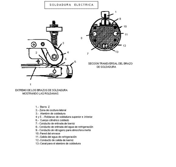
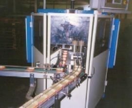
The basic system of Soudronic body making machines comprises a system for feeding flat bodies to the machine, a system for unstacking them, a winding unit and the welding station. In the latter are the arms, which support the wheels. In the lower arm are incorporated all the duct system for the different functions (copper wire, cooling, nitrogen, varnish…). See figure 2. The can body producing machine may also have a cutting unit for double or triple height bodies, a built-in system for welding in an inert atmosphere to avoid the formation of oxide, and a side seam varnishing unit both on the inside and on the outside of the body.
Figure 2: Detail of the ends of the arms
The body of the container, once formed, is mechanically introduced into the welding station, where the overlap is kept constant. The technique used by Soudronic welders is, simply, a continuous discharge welding procedure.
In the WIMA and SUPERWIMA processes, the temperature of the body exceeds 900º C. to guarantee an effective overcoming of the solid phase of the metal along the seam. However, this is considerably lower than the temperatures reached with previous models.
In the Soudronic system, a sinusoidal alternating current input is used. A 50 hertz machine produces 100 discharges (welding spots) per second, and a 500 hertz machine produces 1,000 in the same time.
As we have already indicated, the incorporation of a cutting unit in the welding machine also allows the welding of double height bodies. In addition, this incorporation can increase production with lower welding frequencies, or make it possible to manufacture shorter bodies, which the machine could not handle otherwise. If the container is to be beaded or notched, the welding is done in an atmosphere of inert gas, as it needs to be free of oxide. The formation of an oxide film would be very negative, as it could come off in a later process. The subsequent re-varnishing of the welding area is carried out because the process does not allow varnish to be applied in a flat sheet in the welding area, as it would hinder the passage of current. This varnish is subsequently cured within the manufacturing line.
Soudronic is at the forefront worldwide in the process of side seam electric welding, with thousands of different units operating throughout the world.
2º.- FUNDAMENTALS OF ELECTRIC WELDING
1º.- BASIC SCHEME OF A POINT
A welding point is generated when the metal melts due to the heat developed by the passage of a high intensity current at a low potential difference.
Although there are two types of current, direct and alternating, we know that the normal use is the second. Alternating current (abbreviated AC in Spanish and AC in English) is the electric current in which the magnitude and direction vary cyclically. The waveform of the most commonly used alternating current is that of a sine wave, since a more efficient transmission of energy is achieved. To achieve a high number of welding points per unit of time, the frequency of the alternating current used is increased. Let’s explain the process a little more.
The alternating current at the normal supply frequency of the industrial network, reaches the welding machine, which introduces it into a frequency converter, thus increasing it in a significant number of hertz. Thus, for example, in a specific case it goes from 50 hertz/second – supply frequency – to 500 hertz/second – converter output-.
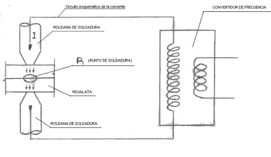
The current intensity at the time of welding is between 1500 and 2000 amps and the voltage or potential difference around 4.5 – 6.5 volts. Therefore, the electric current, conveniently transformed to these conditions of frequency, intensity and voltage, is passed through the welding station, by means of the profiled copper wire and guided by the wheels, acting on the tinplate overlap, to generate a welding point. See figure 3:
Figure 3: Basic scheme of a welding point
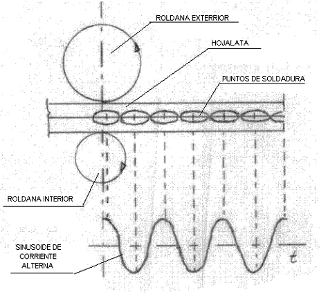
2º.- BASIC SCHEME OF A CONTINUOUS LINE OF WELDING POINTS
Each hertz produces a complete sinusoid in the frequency graph, i.e. two inverse points and therefore two welding points. Therefore, with an output frequency of 500 hertz, 1000 welding points/second are generated. This succession of points gives rise to a continuous weld along the side seam of the can. See figure 4:
Figure 4: Basic scheme for a continuous line of welding points
The union is produced following the following fundamental laws:
– Ohm’s Law. I = V/R
I = intensity of current passing through the circuit
V = potential difference
R = resistance of the system
– Joule’s Law.
Q = heat energy produced by the current and is measured in calories
I = intensity of the current flowing and is measured in amperes
R = electrical resistance of the conductor and is measured in ohms
t = time which is measured in seconds
For a constant Q value, the appropriate one to form a point, the higher the intensity, the less time is required. That is, the time is inversely proportional to the square of the current intensity.
As the heat energy, used for welding, is a function of the square of the intensity, it is evident that it is convenient to make the values of the latter high. It is always of interest to keep the effective value of the current constant, so that there is no variation in the energy that is being used to weld at that moment. The machines have a voltage compensator that automatically varies the opening angle of the alternating current in order to keep the effective value of the same constant.
Unlike the intensity, it is of interest that the welding time is as short as possible since a prolonged time causes:
– Increase of the temperature of the seam without reaching the melting point.
– Increase of losses.
– Deterioration of the electrodes.
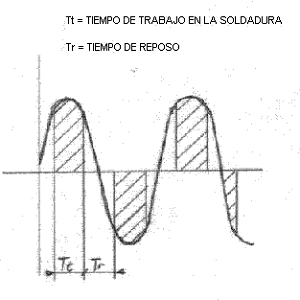
The welding working time is less than that of a half-wave of the sinusoid of a frequency cycle. See figure 5. It is expressed as a percentage of the total area of the half-wave. In practical value, in Soudronic machines it is between 85 to 95%. The remaining percentage is the rest time
Figure 5: Time diagrams
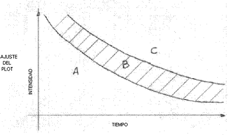
If for the same type of material, the real values of the intensity are represented on a coordinate axis for different welding times in three different cases:
1st.- Without welding
2nd.- When welding occurs
3rd.- When the point burns
we will obtain a graph as indicated in figure 6, in which three different zones are distinguished.
A.- Contact zone without welding
B.- Welding zone
C.- Zone of molten welding projections
3º.- RESISTANCES IN A WELDING POINT
In the welding circuit there are a series of resistances that we will enumerate, for this we will use figure 7:
Figure 7: Resistances involved in a welding point
– Resistance “r”: Groups all the internal resistances of the circuit conductors, welding wheels, support arm, copper wire that acts as an electrode, etc… This resistance will depend on the electrical characteristics of each of these components. As it is a resistance that does not contribute anything to the welding operation of the point, it should be as small as possible so as not to consume energy in a sterile way. Hence, for example, the welding arm is made of copper, although with a small percentage of chromium in order to give it greater hardness and consistency to withstand its mechanical requirements.
– R1: Contact resistance between the upper wheel and the profiled copper wire.
– R2: Contact resistance between the lower wheel and the profiled copper wire.
– Re and R’e: Contact resistances between the copper wire and the tinplate to be welded.
– Ri and R’i: Internal resistances of the two ends of tinplate to be welded.
– Rc: Contact resistance between the two ends of tinplate to be welded.
There are a number of factors that influence the values of these resistances.
Rc, Re and R’e are affected by:
– The adjustment of the machine
– The pressure exerted by the welding wheels. An increase in pressure reduces their values
– Material to be welded: Nature and state of its surface and hardness of the same
– Conductivity of the material. The increase in temperature increases the resistance.
– The dimensions and type of profiling of the copper wire.
– Material and quality of the copper wire.
The listed resistances are classified into two groups:
⦁ A) Useful or effective: These are those that are necessary and actively cooperate in the melting of the material. These are: Ri, R “i and Rc.
They generate an effective energy We.
We = Wi + W” i + Wc
⦁ B) Parasitic and undesirable. These are those that do not contribute anything to said fusion, but are implicit in the system and cannot be eliminated, only try to minimize them. These are: R1,R2, Re and R “e
They generate energy losses Wp.
Wp = W1 + W2+ We +W” e
The losses W1 and W2 can increase depending on the accumulation of tin encrustations in the throat of the wheels, as well as by the wear of said throats.
The total energy needed to weld will be:
Wt = We + Wp
4º.- OXIDATION
During the welding process, the tin that preserves the tinplate in this area, melts and is deposited on the copper wire. Therefore, the steel is unprotected and also at a high temperature. This triggers, in the presence of oxygen from the air, a rapid oxidation.
The energy losses We and W’e, heat the contact surfaces between the copper wire and the external surfaces of the tinplate, contributing to the oxidation of the weld.
The amount of oxide generated is a function of the temperature reached and the time of permanence at the same.
Q oxide = Function (temperature x time)
See figure 8:
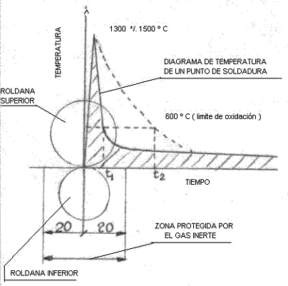
Figure 8: Temperature graph of a welding point
If the temperature drop is slower, the time to descend to the oxidation limit will be longer and therefore the oxidation will be greater.
The presence of oxide negatively affects the welding for several reasons:
– When re-varnishing the seam, the adhesion of the varnish on the oxide is poor and it can come off. Especially if the can is subsequently notched or beaded
– An oxidized stripe appears giving a bad aesthetic presentation.
To avoid oxidation of the weld, a jet of neutral gas (nitrogen) is projected at the welding point at the moment it is made. This gas displaces the presence of air, thus eliminating the oxygen in the area.
5º.- ENERGY NEEDED FOR WELDING
We have seen above that the total energy needed to weld will be:
Wt = We + Wp
The value of this energy is given as a function of the volume of metal to be melted. The volume per second to be melted (Vm) depends on the thickness of the tinplate (e), the overlapped area (c) and the welding speed (Vs). See figure 9:
Figure 9: Overlap of material
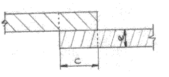
Vm =2e x c x Vs
Other factors that also affect the energy needed are the specific heat of the metal and the heat losses of the system.
These heat losses are important and are linked to several reasons:
– A.) Losses through the copper wire:
– Increase in temperature of the same.
– Wire conductivity
– Contact time between wire and material
– B) Conductivity losses within the metal to be welded
– C) Radiation losses
– D) Losses through the system’s water cooling circuit.
These are difficult to reduce, and the machine manufacturer takes them into account in the design to minimize their value, acting on the system’s insulation, material quality, etc.
6TH.- WELDING PRESSURE
The outer roller transmits a certain pressure to the welding point, which generates an elastic system that acts on the arm. The functions of this pressure are several:
1st.- Keep the two parts of the material overlap in contact
2nd.- Ensure uniform resistance along the entire seam, eliminating possible undulations and roughness of the material.
3rd.- Force the current to pass through the welding point.
4th.- Eliminate air pockets between the parts to be welded.
5th.- Flatten the molten material, reducing the welding thickness.
6th.- Prevent the formation of “commas” and pores.
7th.- Facilitate cooling, ensuring the recrystallization of the material.
8th.- Prevent ejections of molten metal outside the weld.
9th.- Ensure linear displacement of the tube.
Conclusion:
The ideal welding circuit would be one that meets the following conditions:
⦁ a) Minimum losses.
⦁ b) Minimum amount of oxide.
⦁ c) Maximum effective energy
⦁ d) Optimum welding homogeneity.
7TH.- CHARACTERISTICS OF THE METAL TO BE WELDED
The equipment for welding side seams of three-piece cans is designed to use tinplate as the material to be joined. Among the different types, the most common is MR due to its good anticorrosive properties.
The tin protection that covers the steel improves the surfaces in contact, since, being a soft metal, it fills the roughness when subjected to pressure. Consequently, the resistance in the overlapping area decreases.
This tin, when subjected to heat, melts much earlier than the steel. In this state, it must be expelled from the area to be welded so that the two steel parts to be welded are intimately in contact, thus achieving a good mixture of the crystals at the joining point. The expulsion is achieved by the action of the welding pressure.
Therefore, tinplates with high tinning present difficulty in correctly expelling the tin, and those with low coating make it difficult to obtain a good initial contact surface. An intermediate tinning is ideal.
On the other hand, the tinning dirties the throats of the welding rollers, which take it from the dragging by the copper wire.
Chrome and chromium oxide oppose the passage of current. Hence the difficulty of using TFS material.
8TH.- DIMENSIONS OF THE WELDING POINT
A welding point is defined by its three dimensions.
– Length: Depends on the welding speed
– Width: is linked to the overlap.
– Thickness: is a function of the metal thickness.
Length (L):
It is a function of the welding speed, that is, of the copper wire speed and the displacement of the body to be welded. We will define its calculation better by giving a practical example:
We have a welding machine that works at 500 hertz and at a speed of 60m/min.
No. of points/sec. = 500 hertz x 2 = 1000
Welding length/sec. = 60 m. x 1000/ 60 sec. = 1000 mm.
Point length = Welding length/no. of points = 1000 mm/ 1000 points = 1mm
Width (A):
It is a function of the theoretical overlap and slightly greater than it. In the following section (Overlap) we will study this relationship.
Thickness (E):
It is always less than the sum of two thicknesses of the tinplate.
It is called the “crushing coefficient” of the weld, to the constant (K) that multiplied by the tinplate thickness (e), gives us the value of the thickness (E) of the same. The value of this constant (K) must be between 1.40 and 1.60.
1.40< K < 1.60
1.40 e < E < 1.60 e
Hence, the thickness of the weld is always less than twice the thickness of the metal, since crushing occurs due to the action of the pressure of the outer arm.
9TH.- OVERLAP
It is the superposition of material necessary for welding. In machines of a certain cadence, its theoretical value oscillates between 0.2 to 0.4 mm. It is important that its amount remains uniform along the seam, so that the welding points are also uniform. A variation of it would suppose an alteration in the amount of material to be welded, and working with the same parameters, the results would not be equal throughout the weld.
The piece that determines the amount of overlap is the “Z-bar”. It consists of a strip with a Z-section, housed in the welding arm, which receives the edges of the body in its two grooves, which overlap the theoretical value of the overlap.
With a Z of a determined theoretical overlap, we will obtain a real overlap of approximately 0.1 to 0.2 mm. greater. The Z-bar must be very well insulated to avoid its wear by electroerosion, as well as to avoid energy losses.
The theoretical overlap can be calculated as follows:
It starts from the fact that the section S of the overlapped metal remains constant before and after welding.
In it, it must be fulfilled that:
S = C x 2 e (before welding) and S = A x E (after welding)
from where: C x 2e = A x E and C (theoretical overlap) = A x E / 2e
Knowing the thickness of the metal, it will be enough to measure on a weld already made, its thickness (E) and its width (A) to know its theoretical overlap.
To measure E and A, you can act as follows:
Cut two pieces of the seam 10 mm from the ends. See figure 12.
Prepare a specimen with two-component resin with them, polish it and measure with the help of a microscope the dimensions of the section of the weld (E and A) in both sections. Apply the formula below. Making this double determination, it is verified if the overlap remains constant. If not, apart from the possible problems in the welding, we would obtain a conical body.
10.- WELDING METALLURGY
Heating period:
The passage of the current gives rise to a localized heating, which produces the fusion of the metal in both parts to be joined, giving rise to a welding point. The core of this point is called a lens because it has a shape similar to it. During its heating, this metal zone expands. The pressure of the upper roller must be such that it neutralizes the expansion stress of the molten metal. If this pressure is weak, the molten metal escapes in the form of projections. The projections are in themselves a serious defect but also give rise to other internal problems to the welding such as porosities.
Thermal state of the point at the cut of the welding current:
When the current is interrupted, the following zones are distinguished at the point: See figure 13.
Figure 13: Section of a welding point
Zone A: In it, the metal is molten (approximately at 1500º C)
Zone B: Pasty metal at about 1000º C
Zone C: At critical temperature
Zone D: Room temperature
The temperature gradient rises from room temperature to 1500º C in a distance of about 3 mm.
The interruption of the welding current marks the beginning of the cooling with a sharp drop in temperature.
Cooling phase:
The molten metal lens is found within an important refrigerant mass, consisting of:
– The welded body
– The electrodes that are refrigerated
Therefore, the thermal changes are rapid, giving way to the crystallization that is carried out converging towards the center of the point. In zone D there is no change in structure, in the remaining ones there is. In C the grain size decreases and in B and A this decrease is accentuated.
The heat contraction can cause the appearance of internal stresses in the points. In the event that cooling under pressure is not carried out correctly, the formation of blowholes (“commas”) may occur in the weld.
On this last topic, you can see the work: “COMMAS IN WELDING AND ITS MICROGRAPHIC CONTROL”, published on this website.
 Welding on Tinplate Cans
 Causes of wire slippage on welding
 What are the possible causes of a mismatch in a can at the time of welding?
 Food Can Welding: Process and Technology
 what is WIMA WELDING?
Electric welding in metal can manufacture
cold welding problems on your Soudronic welder
Can welding problems
RESISTANCE WELDING WITH ROLLERS
what is WIMA WELDING?
Electric welding in metal can manufacture
cold welding problems on your Soudronic welder
Can welding problems
RESISTANCE WELDING WITH ROLLERS
 ELECTRIC WELDING