1. Introduction
This document discusses Metal Exposure (ME) and the Risk Map for all stages of the aluminum can manufacturing process related to ME.
Metal Exposure is the variable that determines the shelf life of the packaging, and its limit depends on the type of product contained in the can.
The ME variable is the most complex to control, as each stage of the process can affect the ME reading. Even external factors such as the ventilation system or leaks in the roof can cause problems in the ME results.
The objective of this document is to provide an overview of the risks associated with each stage of the can manufacturing process that may influence the Metal Exposure reading.
For readers who are not familiar with the can manufacturing process but would like to learn about aluminum can production, it is recommended to watch the following videos on YouTube:
- HOW IT’S MADE: ALUMINUM CANS
- The Ingenious Design of the Aluminum Beverage Cans
- Manual of the World: How the Aluminum Can is made
2. Main causes of Metal Exposure
Metal Exposure occurs when the varnish does not completely cover the interior metal of the can, generally due to:
- Residues of salt, dirt, or oil that are not properly removed during the washing process.
- Stress areas in the metal that are difficult to coat.
- Irregular thickness of the interior varnish film due to inadequate application parameters.
- Varnish or can temperature outside the appropriate range during application.
- Damage caused by objects that come into contact with the inside of the can during production.
From the author’s perspective, there are key phases of the process in which problems can arise in the control of ME.
3. The environment
Metal Exposure risks associated with the environment:
- Excessive ambient temperatures during varnish application; it is recommended to maintain the ambient temperature below 26 °C.
- Leaks from the roof or ventilation system can cause contaminants to enter the cans during their transfer by the conveyors.
- Oil mist from the Front End can migrate to the Back End, condense, and fall inside the cans, or be sucked in by air tables, single filers, or tunnel tracks blowers.
- Cans overturned in the Washer or before varnish application, if handled incorrectly by operators, can cause contamination of the neck wall.
- Dust accumulation due to air deposits inside the cans or due to damaged or removed air conveyor filters.
The aluminum can production process requires a sanitary environment, with controlled humidity and temperature. Therefore, attention to the ventilation system within the industrial areas, compliance with hygienic practices by operators, and protection of conveyors to prevent spills or contamination—especially after the washing process—are critical control stages.
Can manufacturing plants are divided into two clearly differentiated production areas: Front End and Back End.
The Front End is usually the most contaminated area, as it has a high presence of oil mist from the Cupper and Body Makers processes, as well as water mist generated by the spray nozzles of the Washer. This situation can cause problems if the extraction systems are not adequately designed. In addition, the Washer Dry Oven and the Pre-Wash stages add additional heat to the environment.
The Back End requires higher hygiene standards. Environmental control measures, such as maintaining clean air through air tables, blowers with filters, and vacuum elevators, are essential to minimize contamination risks. The heat generated by the Pin Ovens and the I.B.O., along with variations in ambient temperature, can negatively affect varnish application.
Dust particles present in the manufacturing area can settle inside the cans, potentially affecting Metal Exposure (ME) readings.
Therefore, ME control begins with effective management of the manufacturing environment, especially regarding temperature, humidity, and cleanliness. A properly designed ventilation system plays a key role, highlighting the importance of maintaining positive air pressure, adequate air make-up (air make-up), and well-balanced extraction flows.
Optimal environmental conditions are achieved with at least 15 air changes per hour. The strategic location of extraction and supply fans helps to eliminate excess heat and mist, and promotes airflow from the Back End to the Front End, thus helping to maintain the cleanliness of the cans.
It is also recommended that the Mat Top Conveyors located after the washer remain covered, with sufficient height to facilitate sampling. For further guidance, refer to the corresponding illustration.
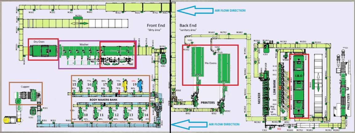
The red rectangles identified in the diagram indicate suitable locations for the installation of extraction fans, in order to facilitate effective heat removal.
The brown rectangles indicate appropriate areas for extraction fans that require special attention to oil condensation, as they are located above areas with a higher concentration of oil mist.
The purple rectangle, located above the Washer, is expected to be exposed to both water and oil mist; therefore, the extraction fans installed in this area should include adequate protection against condensation to prevent dripping onto the Washer.
Metal Exposure Risk Map – Page 3
December / 2025
It is essential that the company responsible for designing the ventilation system incorporates these considerations into its plans.
Additional recommendations
- Use exclusively filtered make-up air (G3), preferably with horizontal supply.
- Ensure that the ceiling fans are equipped with anti-splash systems to prevent leaks during periods of heavy rain.
- Increase air exchange rates and fresh air volume in the hot zones, especially near the ovens.
- All vacuum lifters should have extraction systems ducted to the outside of the plant, and their airflows should be included in the calculation of the total fresh air needed to maintain internal positive pressure.
- Equip the vacuum lifters (Cupper and Body Maker) with mist separators and liquid collection systems for proper treatment, whenever possible with extraction to the outside.
- Perform periodic maintenance of the roof and ventilation system to correct leaks and ensure optimal performance, key aspects to maintain adequate environmental conditions.
- Maintain strict operating practices, such as keeping the exterior access doors closed and preserving the tightness of the production area. This promotes higher internal pressure, prevents dust entry, and prohibits the return of cans from the floor to the conveyors.
Overall, these measures contribute to the effectiveness and reliability of the plant’s ventilation system and environmental control.
4. Transport systems – recommendations to avoid contamination risks
Routine procedures should be implemented for the periodic replacement of filters in all air tables, tunnel tracks, and single filers.
When designing air tables located between the Pin Ovens and the inside sprays, it should be considered that the temperature of the cans does not exceed 26 °C before varnish application. Also, the conveyor design should allow at least 1.5 minutes of accumulation to facilitate line modulation and can cooling.
The design of the Washer infeed conveyor is critical. Cans overturned during the washing process can cause ME-related contamination problems from various stages or spills onto other cans, as well as complications with decorated cans. Ensuring a well-formed pack is essential; therefore, it is recommended to have sufficient length for three tables to control pack formation, and to include a vacuum transfer system before these tables to remove overturned cans before entering the Washer.
The use of a low-friction belt, such as Blue Acetal micro pitch, will help the cans slide correctly and form a proper pack. It is essential to maintain a good conveyor modulation program to support line control both at the inlet and outlet of the Washer.
All conveyors located downstream of the Washer must be equipped with covers to prevent contamination of the already washed cans. Adequate clearance must be ensured between the cover and the top of the can so that they can be easily removed for sampling and inspection. These covers protect against contamination from possible leaks or residues that may enter the washed cans.
5. Compressed air system – recommendations to avoid contamination risks
Typically, manufacturing plants include two types of compressed air systems:
- High pressure and low flow, which feeds the production machines through a high-pressure manifold, generally operating between 80 and 100 psi.
- Low pressure and high flow, typically between 40 and 50 psi, used in manifolds that blow the cans in equipment such as Cuppers, Body Makers, Printers, and Neckers / L.Tester / Optical Inspectors.
Can plants require dry air, without humidity or oil, to maintain optimal performance, especially in the low-pressure systems of all equipment. Preventing contamination inside the cans is crucial; therefore, each blowing system at the equipment inlet must have a 25 μm filter to trap particles generated by oxidation in the pipes. Any particle lodged in the can wall can trigger an ME reading.
Soluble Oil System (S.O.S) – Key risks and controls
- Common problems include dirty cans, incorrect tramp or coolant measurements, inadequate levels of biocide or cup oil, and unstable system parameters such as temperature, bacteria, and pH.
- The S.O.S cools, lubricates, and cleans the tools during can production but accumulates hydraulic oil and grease (tramp), which must be managed to avoid contamination.
- It is essential to maintain adequate concentrations of coolant and tramp, along with correct temperature, pH, and stability, for optimal cleaning and cooling.
- Excess tramp or cup oil can contaminate the cans and cause product defects. Centrifuges are the most effective method for removing tramp, although gravity separators can also work depending on the stability of the S.O.S.
- The stability of the solution is usually around 95%, determined by comparing the tramp reading immediately after collection and from the bottom of the sample after 30 minutes of settling. Stability is controlled by polymer added to the S.O.S solution, forming part of the coolant formulation.
- A low coolant concentration reduces cleaning effectiveness, while an incorrect polymer content can generate high tramp if gravity separation is used.
- Effective operation depends on calibrated monitoring equipment, trained personnel, and automatic dosing systems linked to water replenishment volumes.
- The use of soluble oil and water should be proportional to can production, with daily monitoring recommended to identify leaks.
- Maintaining a stable coolant concentration ensures tool cleaning and minimizes defects.
- Maintain a routine cycle of temperature control, ensuring that the coolant temperature provided by the supplier is maintained by heaters (typically 110⁰F) and that all ducts have thermal insulation.
6. Industrial and deionized water systems
- ME risk in D&I and industrial water systems: hard water can deposit salts on the can walls, causing ME.
- The Washer feed water must have hardness (conductivity) of less than 50 μS/cm for effective ME control.
- Deionized water must be kept always below 5 μS/cm, achieved by deionization columns or reverse osmosis.
7. Cup Production (Cupper)
ME risks associated with the Cupper:
- Hydraulic oil leaks in the press can contaminate the aluminum sheet during cup production, resulting in oil inside the cups that the Washer cannot completely remove.
- This problem can also cause “Die Jam” or “Blushing”.
- Excess cup oil or inadequate combinations of cup oil and Post Lub from the supplier highlight the need for a qualification process when testing new Post Lub from a metal supplier.
- Precise control and measurement of cup oil (approx. 72 mg/ft²/side) is essential, given that the dosage matters for cups of ~12,000 mg.
- The dosage should be linked to the Cupper Stroke, with reliable systems such as the Unist Lubricator System recommended.
- Technical reading recommended: “5th command – Measure it right: Case of measuring the cup oil weight”.
8. Production Process – Body Makers (BMs)
ME risks in Body Maker:
- Dirty punches: Clean and polish the punch at least once per shift and keep the soluble oil tramp under control. Dirty punches darken the inside of the cans, which should be detected and rejected by visual inspection, being a key indicator.
- Excessive Cross Hatch: Excessive pressure in crosshatching creates deep grooves that trap dirt and are difficult to clean. It is recommended to use a Cross Hatch Machine for consistent results instead of manual processing.
(Photo text) Enlarged image of the can wall with ME
After the reaction with sulfate, it is probably due to a dirty punch or excessive cross hatching on the punch.
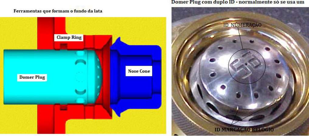
Misalignment of the Bottom Former with punch displacement can generate hidden stresses and deformations in the countersink wall during penetration of the Dome Plug, causing a high level of ME at the bottom of the can. Cans with fractured bottoms often show elevated ME in the countersink, especially before the fracture point during Neck Reforming. The dynamic alignment of the Tool Block and Bottom Former helps control this problem.
The Free Stroke Analyzer (https://www.deltahtechnology.co.uk) can be useful in addressing this situation.
- Worn nose cone and clamping ring: Increase friction during dome formation, causing misalignment and accelerating tool wear.
- Worn Domer Plug radius: Increases friction when forming the bottom of the can.
- Regular inspection and replacement of worn parts is an effective control method.
Enlarged image of the can wall with ME
After the reaction with sulfate, it is probably due to a dirty punch or excessive cross hatching on the punch.
Body Maker (BM) identification marks
Each Body Maker is identified by a label, usually using the Domer Plug number, engraving, or clock mark. Excessive marking can damage the aluminum, causing ME, which is easily identifiable as it occurs consistently in the BM label location.

We must not forget the blow-off. Compressed air can reach the inside of the can in two ways:
- Continuous air strip assist: typically operates in a range of 3 – 5 psi.
- Can strip blow-off: typically operates in a range of 30 – 45 psi.
9. Trimmer Process
The risk of ME associated with the Trimmer process is related to burns on the cut edge of the can. The location of the burn—inside or outside—impacts the formation of the pack at the entrance of the Washer. Internal burns usually cause fewer overturned cans, due to the reduction of friction with the mat top conveyor.
Any step or visible burn on the cut edge can cause problems both in the Washer pack and during penetration of the Necker K/O, causing scratches on the neck and generating ME.
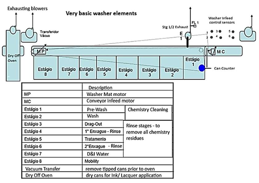
10. Washing Process – Can Washer
The Can Washer is one of the two key pieces of equipment for ME control in the production line. Each step offers a potential for ME as a special cause, but we will focus on those most likely to trigger ME when out of control, rather than listing all the Washer parameters.
The following diagram is a simplified representation of the complex Can Washer, designed solely to guide our analysis of the critical points.
General Comments on Can Manufacturing
The design of the can bottom is closely related to the diameter of its body. Stylized can bottoms require precise attention when opening the countersink area to ensure effective rinsing with the water spray nozzles. Different types or sizes of cans may require different nozzle configurations or an increase in the nozzle distribution per header.
Regarding the height of the can, washing a 50 cl can presents more challenges than cleaning a 33 cl can, and may require different types of nozzles or pressure adjustments to achieve optimal results. In general, solutions developed for the most demanding can size will be even more effective with easier-to-clean cans.
In practice, the transition of a production line from standard 12 oz (211 diameter) cans to stylized 12 oz cans revealed significant operational differences. The absence of ME in the 211 mm diameter was manageable, but when switching to the stylized 12 oz format, initial complications arose. The implementation of new recirculation headers equipped with additional and specialized nozzles effectively helped resolve these issues.
It is worth noting that the improvements made for the stylized 12 oz cans also improved the performance of the standard 12 oz cans.
 Global Metal Cans Market, by Type of Manufacture
 what is the metal exposure test for beverage cans?
 Main defects of a 2pc aluminum can
 Principle of operation of the Bodymaker
Failure of water stain washing machine cans
Principle of operation of the Bodymaker
Failure of water stain washing machine cans
 Water Stains in aluminum Metal Cans
 REDUCTION OF EXPOSURE TO HFI METAL WITH AUTOMATIC LINE-FED ENAMEL CONTROLS
 MANUAL TESTER OF THE METAL PACKAGING HERMETICITY