SUMMARY
A pneumatic equipment is described for separating and raising the top sheet of a package in a sheet metal feeder. This action is achieved by blowing air on said sheet by means of a specially designed nozzle, in this way a vacuum area is created, so that the upper sheet is separated from the pile, and raised so as to be easily fed a to one to the recipient machine (coater, rotary or shear). The equipment is particularly effective in the feeding of aluminum sheets, where magnetic separation is not possible.
INTRODUCTION
It was difficult to separate and correctly deliver aluminum sheets cut in “scroll” – zigzag – from a sheet feeder using a conventional system of magnets mounted on both sides of the pack of sheets, because this material is amagnetic and comparatively with tinplate very light . In addition, the edges of the sheet, as it moves, scratch the varnish film of the lower sheet. This is especially true in older equipment, which works with a simpler technique.
Below is a possibility of improving these old equipment that otherwise work very well. This is achieved by applying a method of air blowing, which allows a smooth delivery of the aluminum sheet eliminating damage. This improvement is also interesting to use in the handling of TFS, since it is a material very sensitive to scratching.
DESCRIPTION OF THE SEPARATOR UNIT
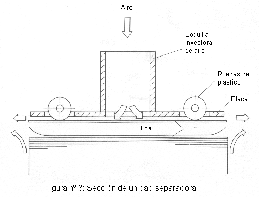
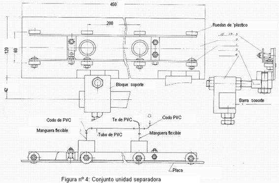
The separating unit or set is suspended on the lifting table, on both sides of the sheet feeder. The stack of sheets is located about 30 mm away from the separating unit. As shown in figure 3, the blown air is supplied from a turbofan to the nozzle located in the upper part of the unit. Through it, the air flows on the sheet, creating a space with negative pressure, with respect to the atmospheric one. This negative pressure separates and floats the top sheet of the stack. When the blade hits the plastic wheels in the separator unit, the vacuum in the general feeder installation is activated, and the suckers grip the blade firmly. Then it is gently fed into the machine.
A series of figures will give a clearer idea of the separating unit.
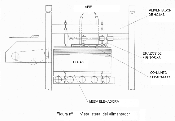
Figure No. 1: Shows a schematic side view of the feeder with the separator assembly above the sheet pack.
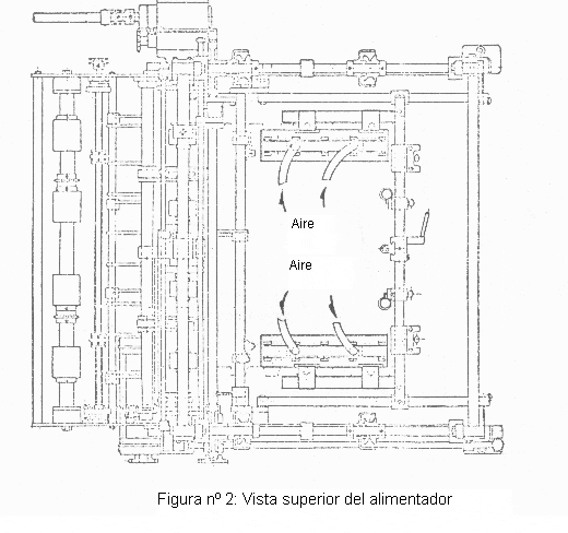
Figure No. 2: It shows a top view of the feeder. To the right and left of the elevation zone the pair of separators are located.
Figure No. 3: A section of the separating unit is simply represented, with the arrival of air, blowing nozzle, contact wheels and air flow on the last sheet of the package.
Figura nº 4: Dibujo de conjunto de la unidad separadora, con sus dimensiones básicas y piezas principales.
SPECIFICATIONS
Air blower: Air supply = 10 m3 / min.
Static pressure = 400cm.water.
Operating speed: 85 sheets / min.
ADVANTAGE
In summary, this improvement provides the following advantages:
– Prevention of defects and improvement of the resulting quality.
– Reduction of rejects
– Reduction of adjustment time
– Improvement of the operation efficiency.






0 Comments